Toyota Camry (XV70): Removal
REMOVAL
CAUTION / NOTICE / HINT
The necessary procedures (adjustment, calibration, initialization or registration) that must be performed after parts are removed and installed, or replaced during sliding roof housing removal/installation are shown below.
Necessary Procedures After Parts Removed/Installed/Replaced|
Replaced Part or Performed Procedure |
Necessary Procedure | Effect/Inoperative Function when Necessary Procedure not Performed |
Link |
|---|---|---|---|
| Initialize panoramic moon roof system (for Sliding Roof) |
|
|
| Initialize panoramic moon roof system (for Roof Sunshade) |
| |
|
Disconnect cable from negative battery terminal |
Perform steering sensor zero point calibration |
Lane Tracing Assist System |
|
|
Pre-collision System | |||
|
Memorize steering angle neutral point |
Parking Assist Monitor System |
| |
|
Panoramic view monitor system |
|
CAUTION:
Some of these service operations affect the SRS airbag system. Read the precautionary notices concerning the SRS airbag system before servicing.
Click here .gif)
.png)
PROCEDURE
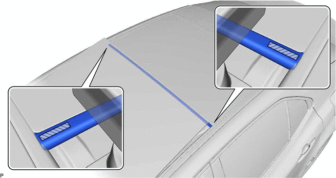
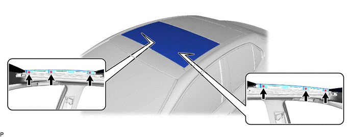
1. REMOVE SLIDING ROOF WEATHERSTRIP
(a) Move the sliding roof glass sub-assembly to the fully tilted up position.
(b) Remove the sliding roof weatherstrip.
.png) |
Double-sided Tape | - |
- |
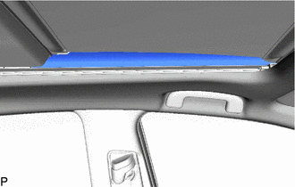
2. REMOVE NO. 3 SLIDING ROOF SIDE GARNISH LH
(a) Move the sunshade trim sub-assembly to the fully opened position.
| (b) Remove the No. 3 sliding roof side garnish LH. |
|
3. REMOVE NO. 3 SLIDING ROOF SIDE GARNISH RH
HINT:
Use the same procedure as for the LH side.
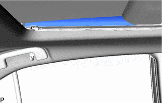
4. REMOVE NO. 4 SLIDING ROOF SIDE GARNISH LH
| (a) Remove the No. 4 sliding roof side garnish LH. |
|
5. REMOVE NO. 4 SLIDING ROOF SIDE GARNISH RH
HINT:
Use the same procedure as for the LH side.
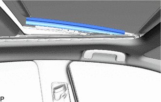
6. REMOVE NO. 2 SLIDING ROOF SIDE GARNISH LH
(a) Move the sliding roof glass sub-assembly to the fully tilted up position.
| (b) Remove the No. 2 sliding roof side garnish LH. |
|
7. REMOVE NO. 2 SLIDING ROOF SIDE GARNISH RH
HINT:
Use the same procedure as for the LH side.
8. REMOVE SLIDING ROOF GLASS SUB-ASSEMBLY
(a) Move the sliding roof glass sub-assembly to the fully closed position.
(b) Using a T25 "TORX" socket wrench, remove the 6 screws and sliding roof glass sub-assembly.
NOTICE:
To prevent the sliding roof glass sub-assembly and sliding roof drive gear assembly from becoming misaligned, move the sliding roof glass sub-assembly to the fully closed position before removing.
9. REMOVE CURTAIN SHIELD AIRBAG ASSEMBLY LH
Click here
10. REMOVE CURTAIN SHIELD AIRBAG ASSEMBLY RH
HINT:
Use the same procedure as for the LH side.
11. REMOVE ROOF ANTENNA ASSEMBLY (w/ Manual (SOS) Switch)
Click here
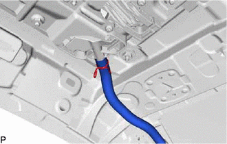
12. DISCONNECT SLIDING ROOF DRAIN HOSE
HINT:
Use the same procedure for all of the sliding roof drain hoses.
| (a) for Clamp Type: (1) Disengage the claw and disconnect the sliding roof drain hose. |
|
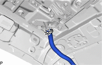
| (b) for Clip Type: (1) Expand the clip and disconnect the sliding roof drain hose. |
|
13. REMOVE FRONT SLIDING ROOF HOUSING MOUNTING BRACKET LH
(a) Remove the bolt, nut and front sliding roof housing mounting bracket LH.
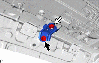
.png) |
Bolt |
.png) |
Nut |
14. REMOVE FRONT SLIDING ROOF HOUSING MOUNTING BRACKET RH
HINT:
Use the same procedure as for the LH side.
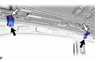
15. REMOVE CENTER SLIDING ROOF HOUSING MOUNTING BRACKET LH
(a) Remove the 2 bolts, 2 nuts and center sliding roof housing mounting bracket LH.
|
|
Bolt |
|
|
Nut |
16. REMOVE CENTER SLIDING ROOF HOUSING MOUNTING BRACKET RH
HINT:
Use the same procedure as for the LH side.
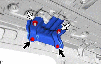
17. REMOVE REAR SLIDING ROOF HOUSING MOUNTING BRACKET LH
(a) Remove the 2 bolts, 2 nuts and 2 rear sliding roof housing mounting brackets LH.
|
|
Bolt |
|
|
Nut |
18. REMOVE REAR SLIDING ROOF HOUSING MOUNTING BRACKET RH
HINT:
Use the same procedure as for the LH side.
19. REMOVE SLIDING ROOF HOUSING ASSEMBLY
(a) Remove the 20 nuts.
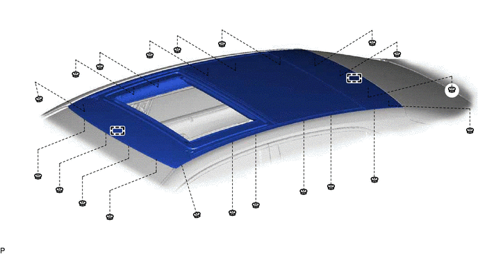
(b) Disengage the 2 guides and remove the sliding roof housing assembly.
READ NEXT:
 Disassembly
DISASSEMBLY PROCEDURE 1. REMOVE NO. 1 SLIDING ROOF SIDE GARNISH LH
(a) Using a heat light, heat the No. 1 sliding roof side garnish LH. Heating Temperature
Item Temperature
No. 1
Reassembly
REASSEMBLY PROCEDURE 1. INSTALL SUNSHADE TRIM SUB-ASSEMBLY
(a) Install the sunshade trim sub-assembly as shown in the illustration.
*A RH Side
*B LH Side
*a Re
Installation
INSTALLATION PROCEDURE 1. INSTALL SLIDING ROOF HOUSING ASSEMBLY
(a) Pass a string under the windshield outside moulding as shown in the illustration.
*1 Windshield Outside Moulding
SEE MORE:
Brake Switch "A" Circuit Open (P057113)
DESCRIPTION The skid control ECU (brake actuator assembly) receives stop light switch assembly signals and uses them to determine whether or not the brakes are applied.
The skid control ECU (brake actuator assembly) has a detection circuit that it uses to detect an open in the stop light input lin
Components
COMPONENTS ILLUSTRATION
*1 AIR CLEANER CAP WITH AIR CLEANER HOSE
*2 ENGINE COOLANT TEMPERATURE SENSOR
*3 VACUUM HOSE
*4 NO. 1 FUEL VAPOR FEED HOSE
*5 NO. 2 VENTILATION HOSE
- -
