
Toyota Camry (XV70): Removal
REMOVAL
PROCEDURE
1. RECOVER REFRIGERANT FROM REFRIGERATION SYSTEM
Click here .gif)
2. REMOVE V-RIBBED BELT
Click here
3. REMOVE COOL AIR INTAKE DUCT SEAL
Click here
4. REMOVE INLET AIR CLEANER ASSEMBLY
Click here
5. DISCONNECT NO. 5 WATER BY-PASS HOSE
Click here
6. DISCONNECT NO. 1 COOLER REFRIGERANT DISCHARGE HOSE SUB-ASSEMBLY
| (a) Remove the bolt and disconnect the No. 1 cooler refrigerant discharge hose sub-assembly from the compressor assembly with pulley. |
|
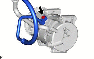
(b) Remove the O-ring from the No. 1 cooler refrigerant discharge hose sub-assembly.
NOTICE:
Seal the openings of the disconnected parts using vinyl tape to prevent moisture and foreign matter from entering them.
7. DISCONNECT SUCTION HOSE SUB-ASSEMBLY
| (a) Remove the bolt and disconnect the suction hose sub-assembly from the compressor assembly with pulley. |
|
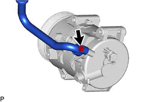
(b) Remove the O-ring from the suction hose sub-assembly.
NOTICE:
Seal the openings of the disconnected parts using vinyl tape to prevent moisture and foreign matter from entering them.
8. REMOVE COMPRESSOR ASSEMBLY WITH PULLEY
| (a) Disconnect the connector. |
|
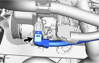
| (b) Disconnect the connector. |
|

(c) for Type A:
(1) Remove the 2 bolts and 2 nuts.
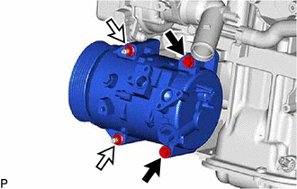
.png) |
Bolt |
.png) |
Nut |
| (2) Using an E8 "TORX" socket wrench, remove the 2 stud bolts and compressor assembly with pulley. |
|
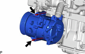
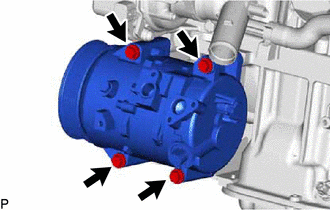
(d) for Type B:
| (1) Remove the 4 bolts and compressor assembly with pulley. |
|
READ NEXT:
SEE MORE:
 Installation
INSTALLATION PROCEDURE 1. INSTALL STEERING WHEEL SWITCH HOUSING
(a) When reusing the steering wheel switch housing:
(1) Using pliers, expand the clamp and temporarily install the steering wheel switch housing as shown in the illustration.
(2) While holding the clamp
Crankshaft Position Sensor "A" Circuit Intermittent (P03351F,P03352A,P033531)
DESCRIPTION Refer to DTC P033511. Click here
DTC No. Detection Item
DTC Detection Condition Trouble Area
MIL Memory
Note P03351F
Crankshaft Position Sensor "A" Circuit Intermittent
Under conditions (a), (b) and (c), no crankshaft position sensor signal
