Toyota Camry (XV70): Terminals Of Ecu
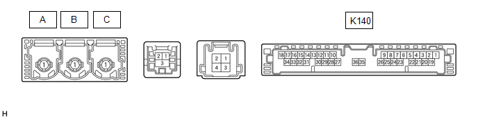
TERMINALS OF ECU
|
Terminal No. (Symbol) | Wiring Color |
Terminal Description | Condition |
Specified Condition |
|---|---|---|---|---|
|
K140-1 (+B) - K140-20 (E) |
B - W-B | Power source (+B) |
Always | 11 to 14 V |
|
K140-3 (SIG-) - K140-20 (E) |
GR - W-B | Ground |
Always | Below 1 V |
|
K140-4 (IND1) - K140-20 (E) |
P - W-B | Manual (SOS) switch red indicator illumination signal |
For 2 seconds after turning the engine switch on (IG) |
1 to 8.5 V |
|
Engine switch off | Below 1 V | |||
|
K140-5 (MCVD) - K140-20 (E) |
B - W-B | Telephone microphone assembly power supply |
Engine switch on (ACC) |
4 to 6 V |
| Engine switch off |
Below 1 V | |||
|
K140-6 (MCI+) - K140-20 (E) |
W - W-B | Receive microphone voice signal |
Voice being input to telephone microphone assembly |
A waveform synchronized with microphone voice signal is input |
|
K140-7 (MCI-) - K140-20 (E) |
R - W-B | Receive microphone voice signal |
Always | Below 1 V |
|
K140-13 (GSW) - K140-20 (E) |
W - W-B | Collision detection signal |
Engine switch on (IG) |
Pulse generation (Refer to waveform1) |
|
K140-19 (IG2) - K140-20 (E) |
LG - W-B |
Power source (IG) | Engine switch on (IG) |
11 to 14 V |
|
Engine switch off | Below 1 V | |||
|
K140-20 (E) - Body ground |
W-B - Body ground | Ground |
Always | Below 1 Ω |
|
K140-21 (SIG1) - K140-3 (SIG-) |
B - G | Manual (SOS) switch button condition signal |
Manual (SOS) switch not pressed |
1.3 to 1.9 V |
|
Manual (SOS) switch pressed |
0.5 to 0.8 V | |||
|
K140-22 (IND2) - K140-20 (E) |
LG - W-B |
Manual (SOS) switch green indicator illumination signal |
For 2 seconds after turning the engine switch on (IG) |
1 to 8.5 V |
|
Engine switch off | Below 1 V | |||
|
K140-23 (SGND) - K140-20 (E) |
Shielded - W-B | Shield ground |
Always | Below 1 Ω |
|
K140-25 (CANP) | R |
CAN communication signal |
- | - |
|
K140-26 (CANN) | W |
CAN communication signal |
- | - |
CHECK DCM (TELEMATICS TRANSCEIVER)
(a) Oscilloscope waveform:
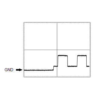
(1) Waveform 1
|
Item | Condition |
|---|---|
|
Tester connection | K140-13 (GSW) - K140-20 (E) |
|
Tool setting | 5.0 V/DIV., 20 ms/DIV. |
|
Vehicle condition | Engine switch on (IG) |
CHECK RADIO AND DISPLAY RECEIVER ASSEMBLY
w/o Navigation System: Click here
.gif)
w/ Navigation System: Click here
READ NEXT:
 Dtc Check / Clear
DTC CHECK / CLEAR CHECK DTC (a) Connect the Techstream to the DLC3.
(b) Turn the engine switch on (IG). (c) Turn the Techstream on.
(d) Enter the following menus: Body Electrical / Telematics / Tr
Data List / Active Test
DATA LIST / ACTIVE TEST DATA LIST NOTICE:
In the table below, the values listed under "Normal Condition" are reference values. Do not depend solely on these reference values when deciding whether a
Diagnostic Trouble Code Chart
DIAGNOSTIC TROUBLE CODE CHART Safety Connect System
DTC No. Detection Item
Link B153711
Telephone Sub Antenna Circuit Short to Ground
B153713 Telephone Sub An
SEE MORE:
Components
COMPONENTS ILLUSTRATION
*1 FUEL PRESSURE SENSOR (FUEL DELIVERY PIPE WITH SENSOR ASSEMBLY)
- -
Adjusting the set speed - Dynamic radar cruise
control
Adjusting the set speed by the switch
To change the set speed, press the "+ RES" or "- SET" switch until the
desired set speed is displayed.
Increases the speed
Decreases the speed
Fine adjustment: Press the switch.
Large adjustment: Press and hold
the switch to change the speed,
