Toyota Camry (XV70): Terminals Of Ecu
TERMINALS OF ECU
CHECK INSTRUMENT PANEL JUNCTION BLOCK ASSEMBLY AND MAIN BODY ECU (MULTIPLEX NETWORK BODY ECU)
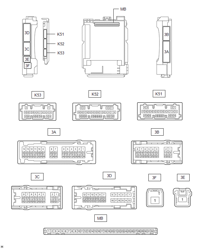
(a) Remove the main body ECU (multiplex network body ECU) from the instrument panel junction block assembly.
Click here .gif)
(b) Reconnect the instrument panel junction block assembly connectors.
(c) Measure the resistance and voltage according to the value(s) in the table below.
HINT:
Measure the values on the wire harness side with the connectors disconnected.
|
Terminal No. (Symbol) |
Wiring Color | Terminal Description |
Condition | Specified Condition |
|---|---|---|---|---|
|
MB-11 (GND1) - Body ground |
- | Ground |
Always | Below 1 Ω |
|
MB-31 (BECU) - Body ground |
- | Battery power supply |
Always | 11 to 14 V |
|
MB-30 (ACC) - Body ground |
- | ACC power supply |
Ignition switch ACC |
11 to 14 V |
|
MB-30 (ACC) - Body ground |
- | ACC power supply |
Ignition switch off |
Below 1 V |
|
MB-32 (IG) - Body ground |
- | IG power supply |
Ignition switch ON |
11 to 14 V |
|
MB-32 (IG) - Body ground |
- | IG power supply |
Ignition switch off |
Below 1 V |
(d) Install the main body ECU (multiplex network body ECU) to the instrument panel junction block assembly.
Click here
(e) Measure the voltage and check for pulses according to the value(s) in the table below.
|
Terminal No. (Symbol) |
Wiring Color | Terminal Description |
Condition | Specified Condition |
|---|---|---|---|---|
|
K52-15 (FUSW) - Body ground |
G - Body ground |
Fuel lid opener switch signal |
Fuel lid opener switch pushed |
Below 1 V |
|
Fuel lid opener switch not pushed |
11 to 14 V | |||
|
K51-24 (FUEL) - Body ground |
G - Body ground | Fuel lid open request signal |
| 11 to 14 V → Below 1 V → 11 to 14 V |
READ NEXT:
 Data List / Active Test
DATA LIST / ACTIVE TEST DATA LIST NOTICE:
In the table below, the values listed under "Normal Condition" are reference values. Do not depend solely on these reference values when deciding whether a
Fuel Lid Opener does not Operate
DESCRIPTION When the fuel lid opener switch is pushed for 0.8 second, the main body ECU (multiplex network ECU) turns on the FUEL OPN relay, and the fuel lid lock with motor assembly opens the fuel li
SEE MORE:
Registration
REGISTRATION PROCEDURE 1. BEFORE REGISTRATION
NOTICE:
The transmitter ID is written on the tire pressure warning valve and transmitter. It is not possible to read the transmitter ID after installing the tire onto the wheel. Therefore, make a note of the transmitter ID before installing the tir
USB Audio System Recognition/Play Error
DESCRIPTION When a USB device or "iPod" is connected to the USB jack of the No. 1 stereo jack adapter assembly, it must have playable files. The device must also communicate with and be recognized by the radio and display receiver assembly. This diagnostic procedure is for when a device is not recog
