Toyota Camry (XV70): Terminals Of Ecu
TERMINALS OF ECU
CHECK MAIN BODY ECU (MULTIPLEX NETWORK BODY ECU) AND INSTRUMENT PANEL JUNCTION BLOCK ASSEMBLY
.png)
(a) Disconnect the instrument panel junction block assembly and main body ECU (multiplex network body ECU) connectors.
(b) Measure the voltage and resistance according to the value(s) in the table below.
|
Terminal No. (Symbol) |
Wiring Color | Terminal Description |
Condition | Specified Condition |
|---|---|---|---|---|
|
3B-3 - Body ground |
W-B - Body ground | Ground |
Always | Below 1 Ω |
|
3C-1 - Body ground |
LG - Body ground | Battery power supply |
Always | 11 to 14 V |
|
3F-1 - Body ground |
W - Body ground | Battery power supply |
Always | 11 to 14 V |
(c) Connect the instrument panel junction block assembly and main body ECU (multiplex network body ECU) connectors.
(d) Measure the voltage and resistance, and check for pulses according to the value(s) in the table below.
|
Terminal No. (Symbol) |
Wiring Color | Terminal Description |
Condition | Specified Condition |
|---|---|---|---|---|
|
3A-40 - Body ground |
LA-G - Body ground |
BKUP LP relay drive output |
Ignition switch off |
Below 1 V |
|
Ignition switch ACC |
11 to 14 V | |||
|
3C-18 - Body ground*1 |
SB - Body ground |
Parking brake switch input |
Parking brake switch on |
Below 1 V |
|
Parking brake switch off |
11 to 14 V | |||
|
3C-19 - Body ground |
BE - Body ground |
BKUP LP relay drive output |
Ignition switch off, shift lever not in R |
Below 1 V |
|
Ignition switch ON, shift lever in R |
11 to 14 V | |||
|
3C-23 - Body ground |
LA-P - Body ground |
BKUP LP relay drive output |
Ignition switch off |
Below 1 V |
|
Ignition switch ON |
11 to 14 V | |||
|
3C-28 - Body ground |
LA-GR - Body ground*2 GR - Body ground*3 |
Daytime running light system drive output |
Daytime running light system operating |
Below 1 V |
|
Daytime running light system not operating |
11 to 14 V | |||
|
3C-31 - Body ground |
V - Body ground | H-LP LH relay drive output |
Light control switch in head position |
Below 1 V |
| Taillights off |
11 to 14 V | |||
|
3C-32 - Body ground |
LA-B - Body ground | Parking lights and front side marker lights drive output |
Taillights on | 11 to 14 V |
|
Taillights off | Below 1 V | |||
|
3D-10 - Body ground |
LG - Body ground |
Back-up lights drive output |
Ignition switch off, shift lever not in R |
Below 1 V |
|
Ignition switch ON, shift lever in R |
11 to 14 V | |||
|
3D-30 - Body ground |
LA-B - Body ground |
Taillights, rear side marker lights and license plate lights drive output |
Taillights on | 11 to 14 V |
|
Taillights off | Below 1 V | |||
|
K51-14 (LLEW) - Body ground |
GR - Body ground | Light control LED ECU LH signal input |
Ignition switch ON, taillights off |
11 to 14 V |
| Ignition switch ON, light control switch in head position |
Pulse generation | |||
|
K51-15 (RLEW) - Body ground |
R - Body ground | Light control LED ECU RH signal input |
Ignition switch ON, taillights off |
11 to 14 V |
|
Ignition switch ON, light control switch in head position |
Pulse generation | |||
|
K51-19 (GND2) - Body ground |
W-B - Body ground | Ground |
Always | Below 1 Ω |
|
K51-23 (AHID) - Body ground |
BE - Body ground |
Auto high beam switch indicator drive output |
Ignition switch ON, auto high beam switch on |
Below 1 V |
|
Ignition switch ON, auto high beam switch off |
11 to 14 V | |||
|
K52-12 (HRY2) - Body ground |
BE - Body ground | H-LP RH relay drive output |
Light control switch in head position |
Below 1 V |
| Taillights off |
11 to 14 V | |||
|
K52-13 (DIM) - Body ground |
G - Body ground | High beam headlight drive output |
Light control switch in head position and dimmer switch in high or high flash position |
Below 1 V |
| Dimmer switch not in high or high flash position |
11 to 14 V | |||
|
K52-16 (HEAD) - Body ground |
LG - Body ground | Light control switch head position input |
Light control switch in head position |
Below 1 V |
| Light control switch not in head position |
11 to 14 V | |||
|
K52-23 (CLTB) - K52-25 (CLTE) |
BE - GR |
Automatic light control sensor power supply output |
Ignition switch off |
Below 1 V |
|
Ignition switch ON |
11 to 14 V | |||
|
K52-24 (CLTS) - Body ground |
R - Body ground |
Automatic light control sensor signal input |
Ignition switch off |
Below 1 V |
|
Ignition switch ON |
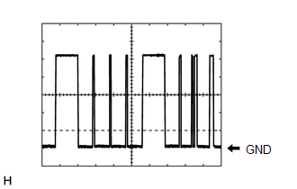
Pulse generation (See waveform 1) | |||
|
K52-26 (AHBI) - Body ground |
B - Body ground | Auto high beam switch signal input |
Auto high beam switch on |
Below 1 V |
| Auto high beam switch off |
11 to 14 V |
- *1: w/o Electric Parking Brake
- *2: for Bulb Type Turn Signal Light
- *3: for LED Type Turn Signal Light
(1) Waveform 1
|
Item | Content |
|---|---|
|
Tester Connection | K52-24 (CLTS) - Body ground |
|
Tool setting | 2 V/DIV., 10 ms./DIV. |
|
Condition | Ignition switch ON |
HINT:
The communication waveform changes according to the surrounding brightness.
CHECK COMBINATION METER ASSEMBLY
Click here
.gif)
CHECK FORWARD RECOGNITION CAMERA
Click here
CHECK STEERING SENSOR
Click here
READ NEXT:
 Dtc Check / Clear
DTC CHECK / CLEAR CHECK FOR DTC (a) Connect the Techstream to the DLC3.
(b) Turn the ignition switch to ON. (c) Turn the Techstream on.
(d) Enter the following menus: Body Electrical / (desired
Freeze Frame Data
FREEZE FRAME DATA FREEZE FRAME DATA (a) Whenever a lighting system DTC is stored, the forward recognition camera stores the current vehicle state as freeze frame data.
CHECK FREEZE FRAME DATA (a) C
Data List / Active Test
DATA LIST / ACTIVE TEST DATA LIST NOTICE:
In the table below, the values listed under "Normal Condition" are reference values. Do not depend solely on these reference values when deciding whether a
SEE MORE:
Removal
REMOVAL CAUTION / NOTICE / HINT
The necessary procedures (adjustment, calibration, initialization or registration) that must be performed after parts are removed and installed, or replaced during air fuel ratio sensor removal/installation are shown below. Necessary Procedures After Parts Removed/I
Left Front Wheel Speed Sensor Circuit Voltage Out of Range (C05001C)
DESCRIPTION Refer to DTC C050012 Click here
DTC No. Detection Item
DTC Detection Condition Trouble Area
C05001C Left Front Wheel Speed Sensor Circuit Voltage Out of Range
When the vehicle is being driven in a straight line at a speed of 20 km/h (12 mph) or mor
