Toyota Camry (XV70): Wiper Switch Signal Mismatch between LIN and Line (B1372)
DESCRIPTION
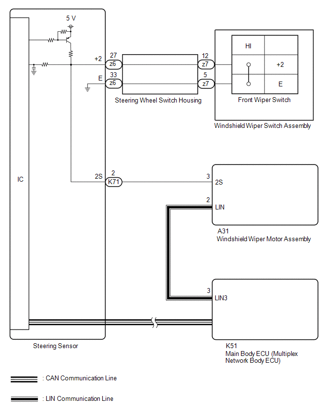
Under normal operation, the windshield wiper motor assembly receives operation signals from the windshield wiper switch assembly via LIN communication.
The windshield wiper motor assembly and windshield wiper switch assembly are also connected via direct line in order to operate the front wipers in HI in an emergency. If the operation signals sent via LIN communication and direct line do not match, this DTC is stored.
|
DTC No. | Detection Item |
DTC Detection Condition |
Trouble Area | Memory |
DTC Output from |
|---|---|---|---|---|---|
|
B1372 | Wiper Switch Signal Mismatch between LIN and Line | Detection condition:
|
| ○ |
Wiper |
WIRING DIAGRAM
CAUTION / NOTICE / HINT
NOTICE:
Before replacing the main body ECU (multiplex network body ECU), refer to Registration.*
Click here .gif)
- *: w/ Smart Key System
PROCEDURE
|
1. | CLEAR DTC |
(a) Connect the Techstream to the DLC3.
(b) Turn the ignition switch to ON.
(c) Turn the Techstream on.
(d) Enter the following menus: Body Electrical / Wiper / Trouble Codes.
(e) Clear the DTCs.
Body Electrical > Wiper > Clear DTCs
|
.gif)
|
2. | CHECK FOR DTC |
(a) Connect the Techstream to the DLC3.
(b) Turn the ignition switch to ON.
(c) Wait 10 seconds or more.
(d) Turn the Techstream on.
(e) Enter the following menus: Body Electrical / Wiper / Trouble Codes.
(f) Check for DTCs.
Body Electrical > Wiper > Trouble Codes|
Result | Proceed to |
|---|---|
|
DTC B1372 is not output |
A |
| DTC B1372 is output |
B |
| A | .gif) |
USE SIMULATION METHOD TO CHECK
|
|
|
3. | READ VALUE USING TECHSTREAM |
(a) Connect the Techstream to the DLC3.
(b) Turn the ignition switch to ON.
(c) Turn the Techstream on.
(d) Enter the following menus: Body Electrical / Wiper / Data List.
(e) Read the Data List according to the display on the Techstream.
Body Electrical > Wiper > Data List|
Tester Display | Measurement Item |
Range | Normal Condition |
Diagnostic Note |
|---|---|---|---|---|
|
Wiper Switch HI (Line) |
Front wiper switch HI position signal (direct line) |
OFF or ON | OFF: Front wiper switch not in HI position ON: Front wiper switch in HI position |
- |
|
Tester Display |
|---|
|
Wiper Switch HI (Line) |
OK:
The Techstream display is normal.
| NG | |
GO TO STEP 7 |
|
|
4. | READ VALUE USING TECHSTREAM |
(a) Connect the Techstream to the DLC3.
(b) Turn the ignition switch to ON.
(c) Turn the Techstream on.
(d) Enter the following menus: Chassis / Steering Angle Sensor / Data List.
(e) Read the Data List according to the display on the Techstream.
Chassis > Steering Angle Sensor > Data List|
Tester Display | Measurement Item |
Range | Normal Condition |
Diagnostic Note |
|---|---|---|---|---|
|
Wiper Hi Switch | Front wiper switch HI position signal |
OFF or ON | OFF: Front wiper switch not in HI position ON: Front wiper switch in HI position |
- |
|
Tester Display |
|---|
|
Wiper Hi Switch |
OK:
The Techstream display is normal.
| NG | |
REPLACE STEERING SENSOR |
|
|
5. | CHECK HARNESS AND CONNECTOR (MAIN BODY ECU (MULTIPLEX NETWORK BODY ECU) - WINDSHIELD WIPER MOTOR ASSEMBLY) |
(a) Disconnect the K51 main body ECU (multiplex network body ECU) connector.
(b) Disconnect the A31 windshield wiper motor assembly connector.
(c) Measure the resistance according to the value(s) in the table below.
Standard Resistance:
|
Tester Connection | Condition |
Specified Condition |
|---|---|---|
|
K51-3 (LIN3) - A31-2 (LIN) |
Always | Below 1 Ω |
|
K51-3 (LIN3) or A31-2 (LIN) - Body ground |
Always | 10 kΩ Higher |
| NG | |
REPAIR OR REPLACE HARNESS OR CONNECTOR |
|
|
6. | CHECK MAIN BODY ECU (MULTIPLEX NETWORK BODY ECU) |
.png)
|
*a | Component without harness connected (Main Body ECU (Multiplex Network Body ECU) |
(a) Check for pulses according to the value(s) in the table below.
Standard Voltage:
|
Tester Connection | Condition |
Specified Condition |
|---|---|---|
|
K51-3 (LIN3) - Body ground |
Ignition switch off |
Below 1 V |
|
Ignition switch ON |
Pulse generation |
| OK | |
REPLACE WINDSHIELD WIPER MOTOR ASSEMBLY |
| NG | |
REPLACE MAIN BODY ECU (MULTIPLEX NETWORK BODY ECU)
|
|
7. | CHECK HARNESS AND CONNECTOR (STEERING SENSOR - WINDSHIELD WIPER MOTOR ASSEMBLY) |
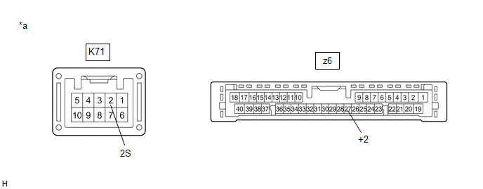
(a) Disconnect the K71 steering sensor connector.
(b) Disconnect the A31 windshield wiper motor assembly connector.
(c) Measure the resistance according to the value(s) in the table below.
Standard Resistance:
|
Tester Connection | Condition |
Specified Condition |
|---|---|---|
|
K71-2 (2S) - A31-3 (2S) |
Always | Below 1 Ω |
|
K71-2 (2S) or A31-3 (2S) - Body ground |
Always | 10 kΩ Higher |
| NG | |
REPAIR OR REPLACE HARNESS OR CONNECTOR |
|
|
8. | INSPECT STEERING SENSOR |
|
*a | Component without harness connected (Steering Sensor) | - |
- |
(a) Remove the steering sensor.
Click here
(b) Measure the resistance according to the value(s) in the table below.
Standard Resistance:
|
Tester Connection | Condition |
Specified Condition |
|---|---|---|
|
K71-2 (2S) - z6-27 (+2) |
Always | Below 1 Ω |
| OK | |
REPLACE WINDSHIELD WIPER MOTOR ASSEMBLY |
| NG | |
REPLACE STEERING SENSOR |
READ NEXT:
SEE MORE:
 Engine (ignition) switch
(vehicles without a
smart key system)
Engine (ignition) switch
(vehicles without a
smart key system)
Starting the engine
1. Check that the parking brake is set.
2. Check that the shift lever is in P.
3. Firmly depress the brake pedal.
4. Turn the engine switch to the "START" position and start the
engine.
Changing the engine switch positions
"LOCK"
The steering wheel is locked and
the
Left Rear Wheel Speed Sensor Internal Electronic Failure (C050C49)
DESCRIPTION When the system is starting up and the skid control ECU (brake actuator assembly) detects a speed sensor circuit malfunction via the speed sensor circuit self-diagnosis function, this DTC is stored.
DTC No. Detection Item
DTC Detection Condition Trouble Area
C050C4
