
Toyota Camry (XV70): Lost Communication with Wiper System LIN BUS (B1373)
DESCRIPTION
The main body ECU (multiplex network body ECU) and windshield wiper motor assembly communicate via LIN communication. The main body ECU (multiplex network body ECU) stores this DTC if communication becomes abnormal.
|
DTC No. | Detection Item |
DTC Detection Condition |
Trouble Area | Memory |
DTC Output from |
|---|---|---|---|---|---|
|
B1373 | Lost Communication with Wiper System LIN BUS | Detection condition:
|
| ○ |
Main Body |
WIRING DIAGRAM
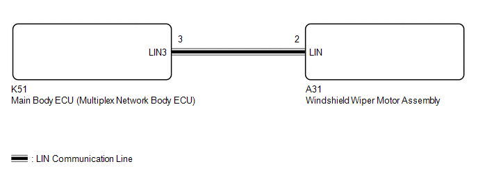
CAUTION / NOTICE / HINT
NOTICE:
Before replacing the main body ECU (multiplex network body ECU), refer to Registration.*
Click here .gif)
- *: w/ Smart Key System
PROCEDURE
|
1. | CHECK HARNESS AND CONNECTOR (MAIN BODY ECU (MULTIPLEX NETWORK BODY ECU) - WINDSHIELD WIPER MOTOR ASSEMBLY) |
(a) Disconnect the K51 main body ECU (multiplex network body ECU) connector.
(b) Disconnect the A31 windshield wiper motor assembly connector.
(c) Measure the resistance according to the value(s) in the table below.
Standard Resistance:
|
Tester Connection | Condition |
Specified Condition |
|---|---|---|
|
K51-3 (LIN3) or A31-2 (LIN) - Body ground |
Always | 10 kΩ Higher |
| NG | .gif) |
REPAIR OR REPLACE HARNESS OR CONNECTOR |
|
.gif)
|
2. | CHECK MAIN BODY ECU (MULTIPLEX NETWORK BODY ECU) |
.png)
|
*a | Component without harness connected (Main Body ECU (Multiplex Network Body ECU) |
(a) Check for pulses according to the value(s) in the table below.
Standard Voltage:
|
Tester Connection | Condition |
Specified Condition |
|---|---|---|
|
K51-3 (LIN3) - Body ground |
Ignition switch off |
Below 1 V |
|
Ignition switch ON |
Pulse generation |
| OK | |
REPLACE WINDSHIELD WIPER MOTOR ASSEMBLY |
| NG | |
REPLACE MAIN BODY ECU (MULTIPLEX NETWORK BODY ECU)
|
READ NEXT:
 Wiper Motor Power Source Circuit
DESCRIPTION This circuit is the power source circuit for the windshield wiper motor assembly. WIRING DIAGRAM
CAUTION / NOTICE / HINT
NOTICE:
Inspect the fuses of circuits related to this
Wiper and Washer Switch Circuit
DESCRIPTION The condition of the windshield wiper switch assembly is detected and sent to the steering sensor in this circuit. WIRING DIAGRAM
PROCEDURE
1. READ VALUE USING TECHSTREAM
Washer Motor Circuit
DESCRIPTION When the windshield washer motor and pump assembly receives signals from the windshield wiper switch assembly it operates to spray washer fluid from the washer nozzle sub-assemblies. WIRIN
SEE MORE:
Disassembly
DISASSEMBLY PROCEDURE 1. REMOVE MAGNET STARTER SWITCH ASSEMBLY
(a) Remove the nut and disconnect the field coil lead wire from the magnet starter switch assembly.
(b) While holding the magnet starter switch assembly to the repair service starter kit, remove the 2 nuts.
Removal
REMOVAL PROCEDURE 1. REMOVE SPARE WHEEL COVER ASSEMBLY
Click here 2. REMOVE SPARE WHEEL COVER TRAY
Click here 3. REMOVE NO. 1 LUGGAGE COMPARTMENT TRIM HOOK
Click here 4. REMOVE REAR FLOOR FINISH PLATE
Click here 5. REMOVE LUGGAGE COMPARTMENT TRIM INNER COVER LH
Click here 6.
