Toyota Camry (XV70): Adjustment
ADJUSTMENT
CAUTION / NOTICE / HINT
|
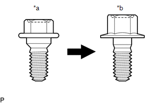
*a | Centering Bolt |
|
*b | Standard Bolt |
HINT:
- Use the same procedure for the RH side and LH side.
- The following procedure is for the LH side.
- Centering bolts are used to install the door hinges to the vehicle body and door. The door cannot be adjusted with the centering bolts installed. Substitute the centering bolts with standard bolts when making adjustments.
- The specified torque for standard bolts is shown in the standard bolt chart.
Click here
.gif)
PROCEDURE
1. INSPECT FRONT DOOR
(a) Check that the clearance measurements of areas a through m are within each standard range.
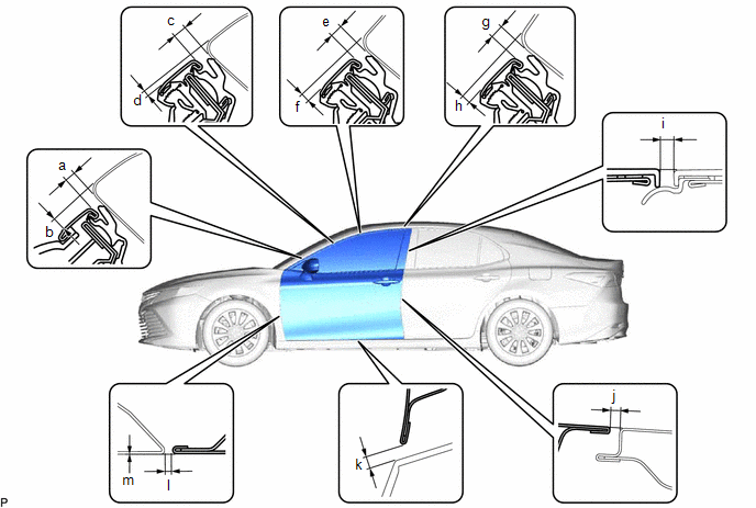 Standard Clearance
 |
Area | Measurement |
Area | Measurement |
|---|---|---|---|
|
a | 3.3 to 6.7 mm (0.130 to 0.264 in.) |
b | 3.5 to 7.5 mm (0.138 to 0.295 in.) |
|
c | 3.3 to 6.7 mm (0.130 to 0.264 in.) |
d | 0.2 to 4.2 mm (0.0079 to 0.165 in.) |
|
e | 3.3 to 6.7 mm (0.130 to 0.264 in.) |
f | 1.2 to 5.2 mm (0.0472 to 0.205 in.) |
|
g | 3.3 to 6.7 mm (0.130 to 0.264 in.) |
h | 1.1 to 5.1 mm (0.0433 to 0.201 in.) |
|
i | 2.3 to 6.3 mm (0.0906 to 0.248 in.) |
j | 4.1 mm (0.161 in.) |
|
k | 5.3 mm (0.209 in.) |
l | 2.6 to 5.0 mm (0.102 to 0.197 in.) |
|
m | -1.2 to 1.2 mm (-0.0472 to 0.0472 in.) |
- | - |
2. ADJUST FRONT DOOR
NOTICE:
Make sure to turn the ignition switch off before adjusting the door lock strikers.
| (a) Using SST, loosen the 4 hinge bolts on the vehicle body and adjust the door position. SST: 09812-00020 |
|
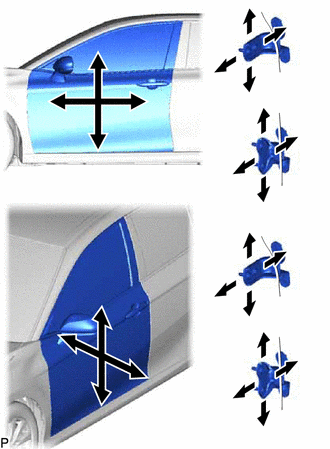
(b) Tighten the 4 hinge bolts on the vehicle body after adjustment.
Torque:
26 N
READ NEXT:
 Reassembly
REASSEMBLY CAUTION / NOTICE / HINT
HINT:
Use the same procedure for the RH side and LH side.
The following procedure is for the LH side.
PROCEDURE 1. PRECAUTION NOTICE:
After tur
Front Door Opening Trim Weatherstrip
ComponentsCOMPONENTS ILLUSTRATION
*1 COWL SIDE TRIM SUB-ASSEMBLY
*2 FRONT DOOR OPENING TRIM WEATHERSTRIP
*3 FRONT DOOR SCUFF PLATE
- - RemovalREMOVAL CAU
SEE MORE:
Brake Pressure Sensor "A" Circuit Voltage Out of Range (C05401C,C054028,C054049)
DESCRIPTION The master cylinder pressure sensor is connected to the skid control ECU in the brake actuator assembly.
DTC No. Detection Item
DTC Detection Condition Trouble Area
C05401C Brake Pressure Sensor "A" Circuit Voltage Out of Range
The voltage of the master
Removal
REMOVAL PROCEDURE 1. REMOVE LOWER STEERING COLUMN COVER SUB-ASSEMBLY
NOTICE: Removing the lower steering column cover sub-assembly in the incorrect order will cause the parts to break.
(a) Release the tilt and telescopic lever and fully extend and lower the steering column assembly.
(b) Lock t
