
Toyota Camry (XV70): Reassembly
REASSEMBLY
CAUTION / NOTICE / HINT
HINT:
- Use the same procedure for the RH side and LH side.
- The following procedure is for the LH side.
PROCEDURE
1. PRECAUTION
NOTICE:
After turning the ignition switch off, waiting time may be required before disconnecting the cable from the negative (-) battery terminal. Therefore, make sure to read the disconnecting the cable from the negative (-) battery terminal notices before proceeding with work.
Click here .gif)
2. INSTALL FRONT DOOR UPPER WINDOW FRAME MOULDING
Click here
3. INSTALL FRONT DOOR REAR OUTSIDE SEAL
| (a) Engage the guide to install the front door rear outside seal. |
|
.png)
4. INSTALL FRONT DOOR REAR WINDOW FRAME MOULDING
Click here
5. INSTALL DOOR WINDOW FRAME MOULDING CLIP
(a) Engage the 2 claws to install the door window frame moulding clip.
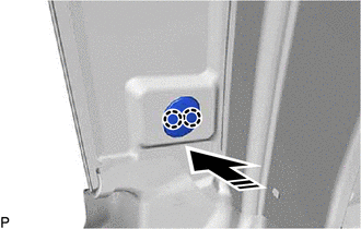
.png) |
Install in this Direction |
6. INSTALL FRONT DOOR FRONT LOWER FRAME UPPER COVER
Click here
7. INSTALL FRONT DOOR BELT MOULDING ASSEMBLY
Click here
8. INSTALL FRONT DOOR NO. 2 WEATHERSTRIP
| (a) Engage the 8 clips to install the front door No. 2 weatherstrip. |
|
.png)
9. INSTALL FRONT DOOR PANEL CUSHION
| (a) Engage the 2 claws to install new front door panel cushion. |
|
.png)
10. INSTALL FRONT DOOR FRONT LOWER FRAME SUB-ASSEMBLY
(a) Engage the guide as shown in the illustration.
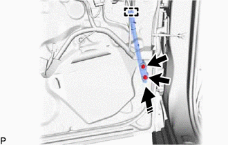
|
|
Install in this Direction |
(b) Install the front door front lower frame sub-assembly with the 2 bolts.
Torque:
8.5 N
READ NEXT:
 Front Door Opening Trim Weatherstrip
ComponentsCOMPONENTS ILLUSTRATION
*1 COWL SIDE TRIM SUB-ASSEMBLY
*2 FRONT DOOR OPENING TRIM WEATHERSTRIP
*3 FRONT DOOR SCUFF PLATE
- - RemovalREMOVAL CAU
Components
COMPONENTS ILLUSTRATION
*1 LUGGAGE COMPARTMENT TRIM INNER COVER LH
*2 NO. 1 LUGGAGE COMPARTMENT TRIM HOOK
*3 REAR FLOOR FINISH PLATE
*4 SPARE WHEEL COVER AS
SEE MORE:
Disassembly
DISASSEMBLY PROCEDURE 1. REMOVE MAGNET STARTER SWITCH ASSEMBLY
(a) Remove the nut and disconnect the field coil lead wire from the magnet starter switch assembly.
(b) While holding the magnet starter switch assembly to the repair service starter kit, remove the 2 nuts.
Crankshaft Position Sensor "A" Circuit Intermittent (P03351F,P03352A,P033531)
DESCRIPTION Refer to DTC P033511. Click here
DTC No. Detection Item
DTC Detection Condition Trouble Area
MIL Memory
Note P03351F
Crankshaft Position Sensor "A" Circuit Intermittent
Under conditions (a), (b) and (c), no crankshaft position sensor signal
