Toyota Camry (XV70): Components
COMPONENTS
ILLUSTRATION
|
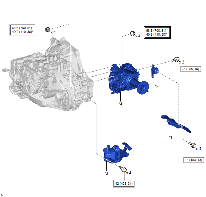
*1 | PROPELLER SHAFT HEAT INSULATOR |
*2 | NO. 1 PROPELLER SHAFT HEAT INSULATOR BRACKET SUB-ASSEMBLY |
|
*3 | REAR ENGINE MOUNTING BRACKET SUB-ASSEMBLY |
*4 | TRANSFER ASSEMBLY |
.png) |
Tightening torque for "Major areas involving basic vehicle performance such as moving/turning/stopping": N*m (kgf*cm, ft.*lbf) |
.png) |
N*m (kgf*cm, ft.*lbf): Specified torque |
|
* | For use with SST and a union nut wrench |
- | - |
ILLUSTRATION
|
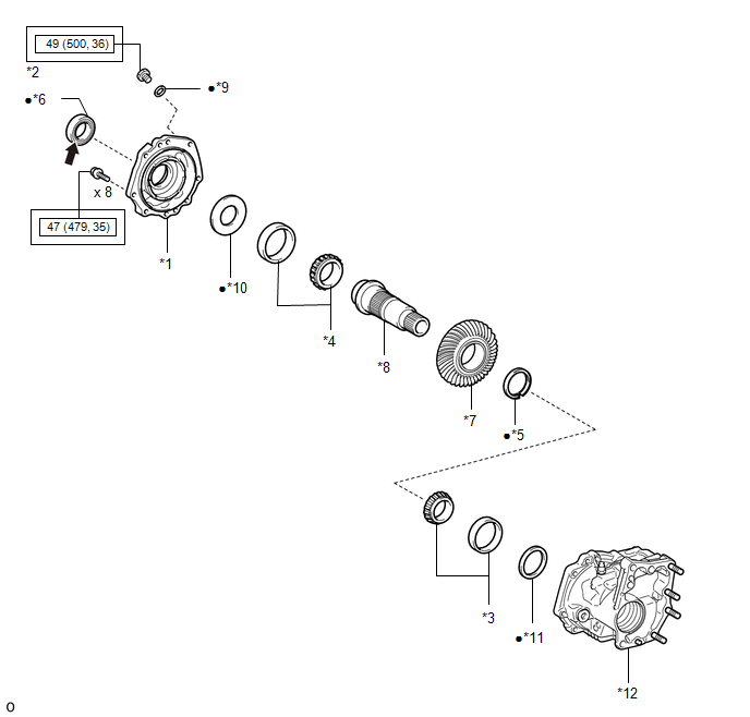
*1 | NO. 1 TRANSFER CASE COVER |
*2 | NO. 1 TRANSFER CASE PLUG |
|
*3 | RING GEAR MOUNTING CASE BEARING LH |
*4 | RING GEAR MOUNTING CASE BEARING RH |
|
*5 | SHAFT SNAP RING |
*6 | TRANSFER CASE OIL SEAL RH |
|
*7 | TRANSFER RING GEAR |
*8 | TRANSFER RING GEAR MOUNTING CASE |
|
*9 | GASKET |
*10 | NO. 2 TRANSFER RING GEAR MOUNTING CASE WASHER |
|
*11 | NO. 1 RING GEAR MOUNTING CASE WASHER |
*12 | TRANSFER CASE |
|
|
Tightening torque for "Major areas involving basic vehicle performance such as moving/turning/stopping": N*m (kgf*cm, ft.*lbf) |
● | Non-reusable part |
.png) |
MP grease | - |
- |
ILLUSTRATION
|
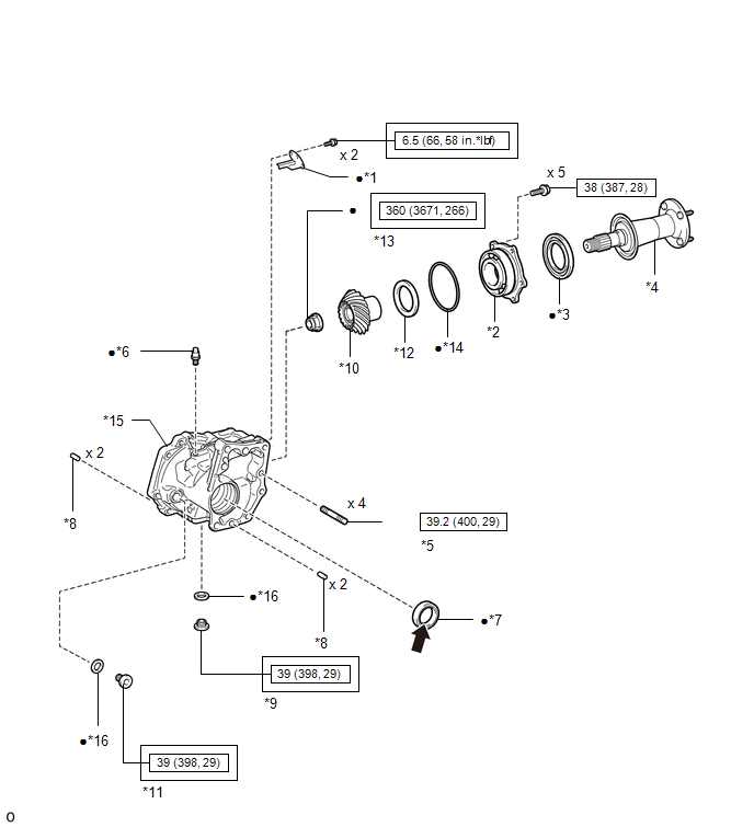
*1 | BREATHER OIL DEFLECTOR |
*2 | FRONT TRANSFER DRIVEN PINION BEARING |
|
*3 | REAR TRANSFER OUTPUT SHAFT DUST DEFLECTOR |
*4 | REAR TRANSFER OUTPUT SHAFT SUB-ASSEMBLY |
|
*5 | TRANSFER AND TRANSAXLE SETTING STUD BOLT |
*6 | TRANSFER CASE BREATHER PLUG |
|
*7 | TRANSFER CASE OIL SEAL |
*8 | TRANSFER CASE STRAIGHT PIN |
|
*9 | TRANSFER DRAIN PLUG |
*10 | TRANSFER DRIVEN PINION |
|
*11 | TRANSFER FILLER PLUG |
*12 | TRANSFER OUTPUT SHAFT WASHER |
|
*13 | TRANSFER GEAR NUT |
*14 | O-RING |
|
*15 | TRANSFER CASE |
*16 | GASKET |
|
|
Tightening torque for "Major areas involving basic vehicle performance such as moving/turning/stopping": N*m (kgf*cm, ft.*lbf) |
|
N*m (kgf*cm, ft.*lbf): Specified torque |
|
● | Non-reusable part |
|
MP grease |
|
★ | Precoated part |
- | - |
READ NEXT:
 Removal
REMOVAL CAUTION / NOTICE / HINT
The necessary procedures (adjustment, calibration, initialization or registration) that must be performed after parts are removed and installed, or replaced during tr
Disassembly
DISASSEMBLY CAUTION / NOTICE / HINT
NOTICE: Before installation of each part, thoroughly clean and dry it. Then apply grease or oil as necessary. Do not use alkaline chemicals to clean aluminum part
Reassembly
REASSEMBLY CAUTION / NOTICE / HINT
NOTICE: Steps 9 to 16 are temporary reassembly procedures for adjustment purposes. PROCEDURE
1. INSTALL BREATHER OIL DEFLECTOR
(a) Install a new breather oil
SEE MORE:
Components
COMPONENTS ILLUSTRATION
*1 REAR LOWER STABILIZER BRACKET
*2 REAR NO. 1 STABILIZER BAR BRACKET
*3 REAR STABILIZER BAR
*4 REAR STABILIZER BUSHING
*5 REAR STABILIZER LINK ASSEMBLY LH
*6 REAR STABILIZER LINK ASSEMBLY RH
Tightening to
Brake Switch "A" Signal Compare Failure (P057162)
DESCRIPTION When the brake pedal is depressed, the stop light switch assembly outputs a signal to the ECM. The ECM uses this signal to control cancellation of vehicle speed by the dynamic radar cruise control. When the ECM determines that terminals STP and ST1- of the stop light switch assembly are
