Toyota Camry (XV70): Components
COMPONENTS
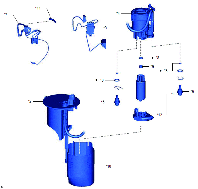
ILLUSTRATION
|
*1 | FUEL PUMP |
*2 | FUEL SUCTION PLATE SUB-ASSEMBLY |
|
*3 | FUEL SENDER GAUGE ASSEMBLY |
*4 | FUEL FILTER |
|
*5 | FUEL MAIN VALVE ASSEMBLY (for Low Pressure) |
*6 | FUEL MAIN VALVE ASSEMBLY (for High Pressure) |
|
*7 | FUEL PUMP HARNESS |
*8 | O-RING |
|
*9 | FUEL PUMP SPACER |
*10 | FUEL SUB-TANK |
|
*11 | HARNESS PROTECTOR |
*12 | SUCTION FILTER |
|
● | Non-reusable part |
- | - |
READ NEXT:
 Removal
REMOVAL CAUTION / NOTICE / HINT
The necessary procedures (adjustment, calibration, initialization or registration) that must be performed after parts are removed and installed, or replaced during fu
Installation
INSTALLATION PROCEDURE 1. INSTALL FUEL MAIN VALVE ASSEMBLY
(a) Apply gasoline to 2 new O-rings. Then install the O-rings to the fuel main valve assembly (for Low Pressure).
(b) Apply gasoline to 2
SEE MORE:
Removal
REMOVAL CAUTION / NOTICE / HINT
HINT:
Use the same procedure for the RH side and LH side.
The following procedure is for the LH side.
PROCEDURE 1. REMOVE FRONT DOOR LOWER FRAME BRACKET GARNISH
Click here
2. REMOVE FRONT DOOR ARMREST COVER SUB-ASSEMBLY
Click here
3. REMOVE
Reassembly
REASSEMBLY CAUTION / NOTICE / HINT
HINT:
Use the same procedure for the RH side and LH side.
The following procedure is for the LH side.
PROCEDURE 1. INSTALL SIDE TURN SIGNAL LIGHT ASSEMBLY (w/ Side Turn Signal Light)
Click here 2. INSTALL NO. 2 OUTER MIRROR COVER (for Type A
© 2023-2026 Copyright www.tocamry.com
