Toyota Camry (XV70): Components
COMPONENTS
ILLUSTRATION
|
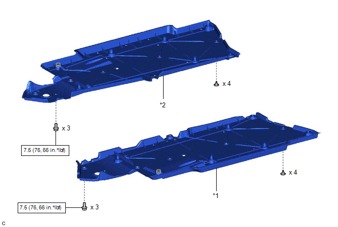
*1 | FRONT FLOOR COVER LH |
*2 | FRONT FLOOR COVER RH |
.png) |
N*m (kgf*cm, ft.*lbf): Specified torque |
- | - |
ILLUSTRATION
|
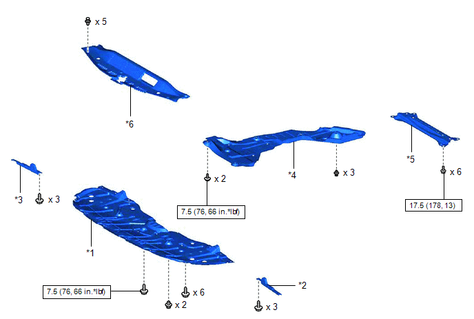
*1 | NO. 1 ENGINE UNDER COVER |
*2 | FRONT WHEEL OPENING EXTENSION PAD LH |
|
*3 | FRONT WHEEL OPENING EXTENSION PAD RH |
*4 | REAR ENGINE UNDER COVER RH |
|
*5 | BODY MOUNTING PLATE |
*6 | COOL AIR INTAKE DUCT SEAL |
|
|
N*m (kgf*cm, ft.*lbf): Specified torque |
- | - |
ILLUSTRATION
|
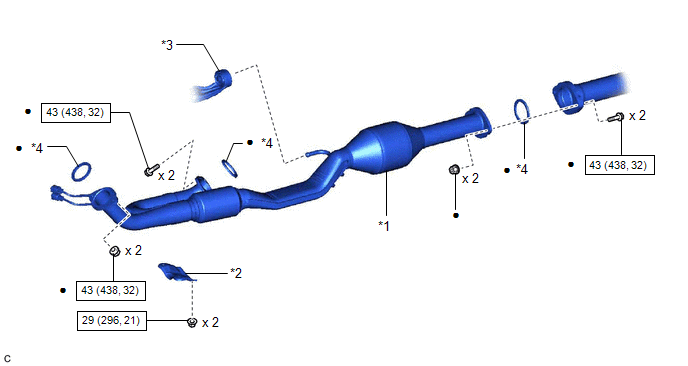
*1 | FRONT EXHAUST PIPE ASSEMBLY |
*2 | NO. 1 EXHAUST PIPE SUPPORT BRACKET (for Lower Side) |
|
*3 | GASKET |
- | - |
|
|
N*m (kgf*cm, ft.*lbf): Specified torque |
● | Non-reusable part |
ILLUSTRATION
|
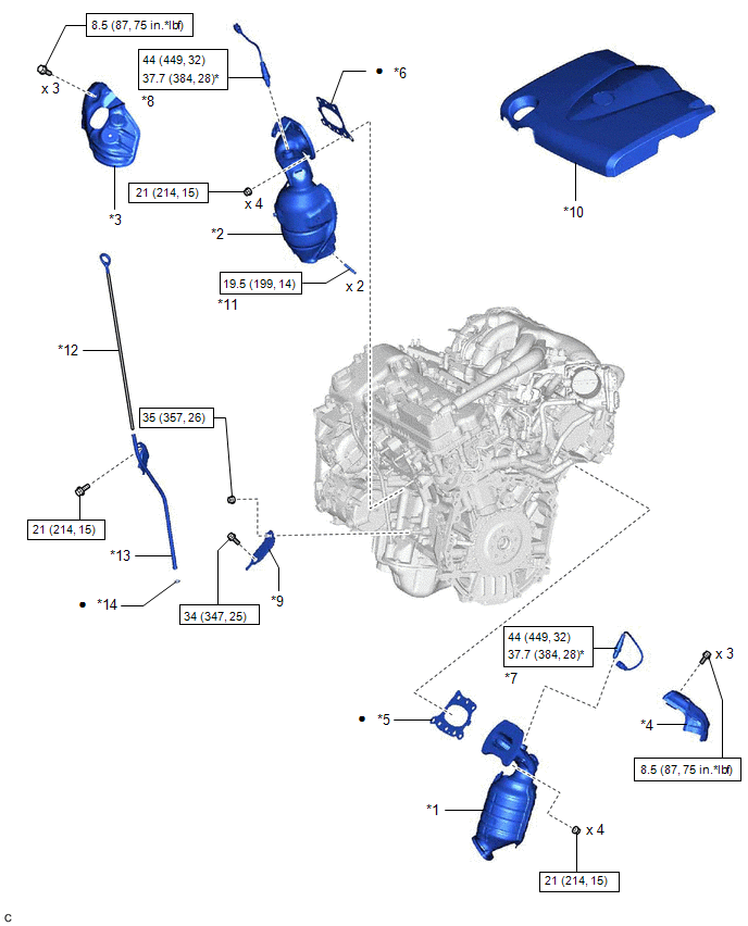
*1 | EXHAUST MANIFOLD ASSEMBLY RH (TWC: Front Catalyst) |
*2 | EXHAUST MANIFOLD ASSEMBLY LH (TWC: Front Catalyst) |
|
*3 | NO. 2 EXHAUST MANIFOLD HEAT INSULATOR |
*4 | NO. 1 EXHAUST MANIFOLD HEAT INSULATOR |
|
*5 | EXHAUST MANIFOLD TO HEAD GASKET (for Bank 1) |
*6 | EXHAUST MANIFOLD TO HEAD GASKET (for Bank 2) |
|
*7 | AIR FUEL RATIO SENSOR (for Bank 1) |
*8 | AIR FUEL RATIO SENSOR (for Bank 2) |
|
*9 | NO. 2 MANIFOLD STAY |
*10 | V-BANK COVER SUB-ASSEMBLY |
|
*11 | STUD BOLT |
*12 | ENGINE OIL LEVEL DIPSTICK |
|
*13 | ENGINE OIL LEVEL DIPSTICK GUIDE |
*14 | ENGINE OIL LEVEL DIPSTICK GUIDE O-RING |
|
|
N*m (kgf*cm, ft.*lbf): Specified torque |
* | For use with SST |
|
● | Non-reusable part |
- | - |
READ NEXT:
 Removal
REMOVAL CAUTION / NOTICE / HINT
The necessary procedures (adjustment, calibration, initialization or registration) that must be performed after parts are removed and installed, or replaced during ex
Installation
INSTALLATION PROCEDURE 1. INSTALL STUD BOLT
HINT: If a stud bolt is deformed or its threads are damaged, replace it.
(a) Using an E8 "TORX" socket wrench, install the 2 stud bolts to the exhau
Components
COMPONENTS ILLUSTRATION
*1 FRONT FLOOR COVER LH
*2 FRONT FLOOR COVER RH
N*m (kgf*cm, ft.*lbf): Specified torque
- - ILLUSTRATION
*1 NO. 1 ENG
SEE MORE:
Replacement
REPLACEMENT CAUTION / NOTICE / HINT
The necessary procedures (adjustment, calibration, initialization or registration) that must be performed after parts are removed and installed, or replaced during automatic transaxle fluid replacement are shown below. Necessary Procedures After Parts Removed/In
Differential Oil
ComponentsCOMPONENTS ILLUSTRATION
*1 REAR DIFFERENTIAL FILLER PLUG
*2 REAR DIFFERENTIAL DRAIN PLUG
*3 GASKET
- -
N*m (kgf*cm, ft.*lbf): Specified torque
● Non-reusable part On-vehicle InspectionON-VEHICLE INSPECTION PROCEDURE
1.
