Toyota Camry (XV70): Components
COMPONENTS
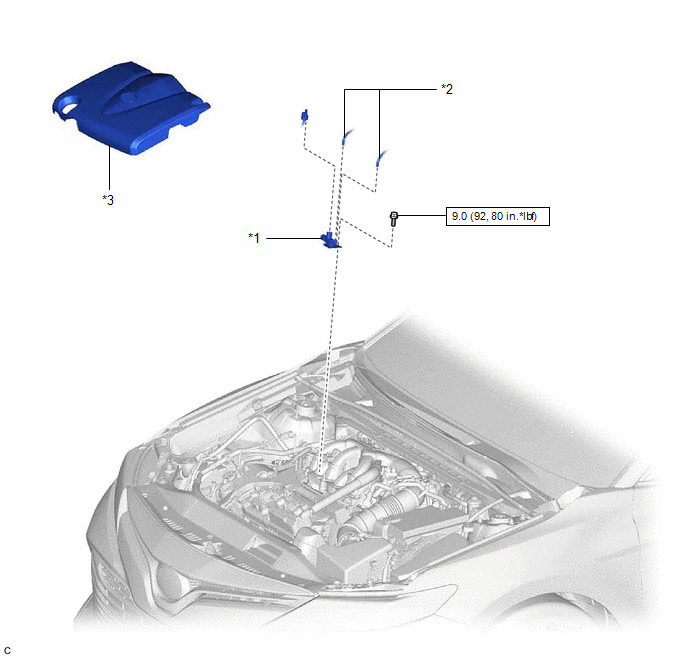
ILLUSTRATION
|
*1 | NO. 1 VACUUM SWITCHING VALVE ASSEMBLY (for ACIS) |
*2 | VACUUM HOSE SUB-ASSEMBLY |
|
*3 | V-BANK COVER SUB-ASSEMBLY |
- | - |
.png) |
N*m (kgf*cm, ft.*lbf): Specified torque |
- | - |
READ NEXT:
 Removal
REMOVAL PROCEDURE 1. REMOVE V-BANK COVER SUB-ASSEMBLY
Click here
2. REMOVE NO. 1 VACUUM SWITCHING VALVE ASSEMBLY (for ACIS)
(a) Disconnect the No. 1 vacuum switching valve assembly
Inspection
INSPECTION PROCEDURE 1. INSPECT NO. 1 VACUUM SWITCHING VALVE ASSEMBLY (for ACIS)
(a) Measure the resistance according to the value(s) in the table below.
Standard Resistance:
Tester C
Installation
INSTALLATION PROCEDURE 1. INSTALL NO. 1 VACUUM SWITCHING VALVE ASSEMBLY (for ACIS)
(a) Install the No. 1 vacuum switching valve assembly (for ACIS) to the intake air surge tank assembly with the bol
SEE MORE:
Disassembly
DISASSEMBLY CAUTION / NOTICE / HINT
HINT:
Use the same procedure for the RH side and LH side.
The following procedure is for the LH side.
PROCEDURE 1. REMOVE FRONT TURN SIGNAL LIGHT BULB (for Bulb Type Turn Signal Light)
(a) Turn the front turn signal light socket with the fron
Components
COMPONENTS ILLUSTRATION
*A for Front Passenger Side
*B for Driver Side
*C w/o Courtesy Light
*D w/ Courtesy Light
*1 COURTESY LIGHT ASSEMBLY
*2 FRONT ARMREST ASSEMBLY
*3 FRONT DOOR ARMREST COVER SUB-ASSEMBLY
*4 FRONT DOOR INNE
© 2023-2026 Copyright www.tocamry.com
