Toyota Camry (XV70): Removal
REMOVAL
PROCEDURE
1. REMOVE V-BANK COVER SUB-ASSEMBLY
Click here .gif)
2. REMOVE NO. 1 VACUUM SWITCHING VALVE ASSEMBLY (for ACIS)
| (a) Disconnect the No. 1 vacuum switching valve assembly (for ACIS) connector. |
|
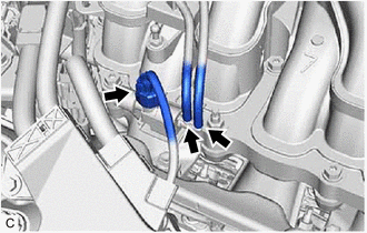
(b) Disconnect the 2 vacuum hose assemblies from the No. 1 vacuum switching valve assembly (for ACIS).
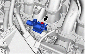
| (c) Remove the bolt and No. 1 vacuum switching valve assembly (for ACIS) from the intake air surge tank assembly. |
|
READ NEXT:
 Inspection
INSPECTION PROCEDURE 1. INSPECT NO. 1 VACUUM SWITCHING VALVE ASSEMBLY (for ACIS)
(a) Measure the resistance according to the value(s) in the table below.
Standard Resistance:
Tester C
Installation
INSTALLATION PROCEDURE 1. INSTALL NO. 1 VACUUM SWITCHING VALVE ASSEMBLY (for ACIS)
(a) Install the No. 1 vacuum switching valve assembly (for ACIS) to the intake air surge tank assembly with the bol
Components
COMPONENTS ILLUSTRATION
*1 NO. 1 VACUUM SWITCHING VALVE ASSEMBLY (for ACIS)
*2 VACUUM HOSE SUB-ASSEMBLY
*3 V-BANK COVER SUB-ASSEMBLY
- -
N*m (kgf*c
SEE MORE:
Terminals Of Ecu
TERMINALS OF ECU TERMINALS OF ECU
*a Component without harness connected
(Skid Control ECU (Brake Actuator Assembly))
- -
HINT:
As a waterproof connector is used for the brake actuator assembly, voltage and waveform inspections cannot be performed with the connector c
Replacement
REPLACEMENT CAUTION / NOTICE / HINT
The necessary procedures (adjustment, calibration, initialization or registration) that must be performed after parts are removed and installed, or replaced during automatic transaxle fluid replacement are shown below. Necessary Procedures After Parts Removed/In
© 2023-2026 Copyright www.tocamry.com
