Toyota Camry (XV70): Inspection
INSPECTION
PROCEDURE
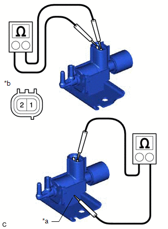
1. INSPECT NO. 1 VACUUM SWITCHING VALVE ASSEMBLY (for ACIS)
| (a) Measure the resistance according to the value(s) in the table below. Standard Resistance:
If the result is not as specified, replace the No. 1 vacuum switching valve assembly (for ACIS). |
|
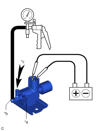
(b) Check the No. 1 vacuum switching valve assembly (for ACIS) operation.
| (1) When vacuum is applied to the port (E), check that air is sucked into the filter. If the result is not as specified, replace the No. 1 vacuum switching valve assembly (for ACIS). |
|

| (2) Apply battery voltage across the terminals. When vacuum is applied to the port (F), check that air is sucked into the port (E). If the result is not as specified, replace the No. 1 vacuum switching valve assembly (for ACIS). |
|
READ NEXT:
 Installation
INSTALLATION PROCEDURE 1. INSTALL NO. 1 VACUUM SWITCHING VALVE ASSEMBLY (for ACIS)
(a) Install the No. 1 vacuum switching valve assembly (for ACIS) to the intake air surge tank assembly with the bol
Components
COMPONENTS ILLUSTRATION
*1 NO. 1 VACUUM SWITCHING VALVE ASSEMBLY (for ACIS)
*2 VACUUM HOSE SUB-ASSEMBLY
*3 V-BANK COVER SUB-ASSEMBLY
- -
N*m (kgf*c
Removal
REMOVAL PROCEDURE 1. REMOVE V-BANK COVER SUB-ASSEMBLY
Click here
2. REMOVE NO. 1 VACUUM SWITCHING VALVE ASSEMBLY (for ACIS)
(a) Disconnect the No. 1 vacuum switching valve assembly
SEE MORE:
On-vehicle Inspection
ON-VEHICLE INSPECTION PROCEDURE
1. INSPECT COOLING FAN SYSTEM CAUTION: To prevent injury due to contact with an operating cooling fan, keep your hands and clothing away from the cooling fan when inspecting the cooling fan system.
(a) Connect the Techstream to the DLC3.
(b) Turn the engine swi
Pressure Control Solenoid "A" Actuator Stuck Off (P07457F)
DESCRIPTION Based on signals from the transmission revolution sensors (NT and NC), the actual gear is detected.
The ECM compares the actual gear with the shift schedule in the ECM memory to detect mechanical malfunctions of the solenoid valves, transmission valve body assembly and automatic transa
