Toyota Camry (XV70): Components
COMPONENTS
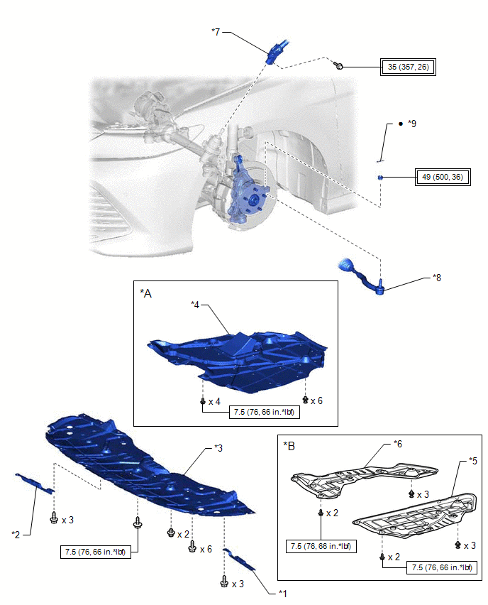
ILLUSTRATION
|
*A | for A25A-FKS |
*B | for 2GR-FKS |
|
*1 | FRONT WHEEL OPENING EXTENSION PAD LH |
*2 | FRONT WHEEL OPENING EXTENSION PAD RH |
|
*3 | NO. 1 ENGINE UNDER COVER |
*4 | NO. 2 ENGINE UNDER COVER ASSEMBLY |
|
*5 | REAR ENGINE UNDER COVER LH |
*6 | REAR ENGINE UNDER COVER RH |
|
*7 | STEERING INTERMEDIATE SHAFT ASSEMBLY |
*8 | TIE ROD ASSEMBLY LH |
|
*9 | COTTER PIN |
- | - |
.png) |
Tightening torque for "Major areas involving basic vehicle performance such as moving/turning/stopping": N*m (kgf*cm, ft.*lbf) |
.png) |
N*m (kgf*cm, ft.*lbf): Specified torque |
|
● | Non-reusable part |
- | - |
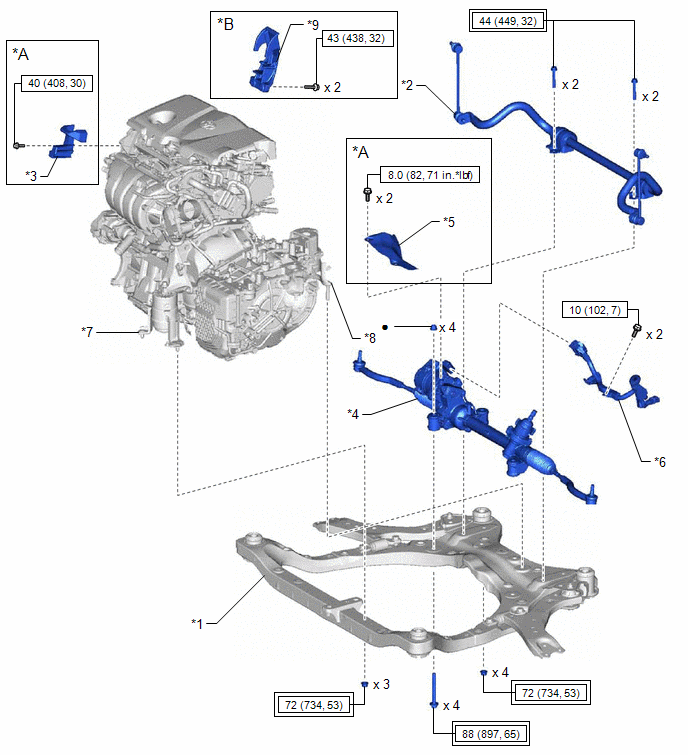
ILLUSTRATION
|
*A | for A25A-FKS |
*B | for AWD |
|
*1 | FRONT FRAME ASSEMBLY |
*2 | FRONT STABILIZER BAR WITH BRACKET |
|
*3 | FUEL DELIVERY GUARD |
*4 | RACK AND PINION POWER STEERING GEAR ASSEMBLY |
|
*5 | STEERING GEAR HEAT INSULATOR |
*6 | WIRE HARNESS |
|
*7 | FRONT ENGINE MOUNTING INSULATOR |
*8 | REAR ENGINE MOUNTING INSULATOR |
|
*9 | FUEL PUMP PROTECTOR |
- | - |
|
|
Tightening torque for "Major areas involving basic vehicle performance such as moving/turning/stopping": N*m (kgf*cm, ft.*lbf) |
|
N*m (kgf*cm, ft.*lbf): Specified torque |
|
● | Non-reusable part |
- | - |
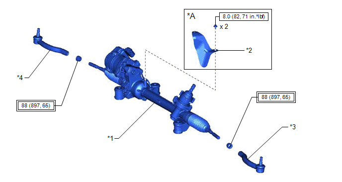
ILLUSTRATION
|
*A | for 2GR-FKS |
- | - |
|
*1 | RACK AND PINION POWER STEERING GEAR ASSEMBLY |
*2 | STEERING GEAR HEAT INSULATOR |
|
*3 | TIE ROD ASSEMBLY LH |
*4 | TIE ROD ASSEMBLY RH |
|
|
Tightening torque for "Major areas involving basic vehicle performance such as moving/turning/stopping": N*m (kgf*cm, ft.*lbf) |
|
N*m (kgf*cm, ft.*lbf): Specified torque |
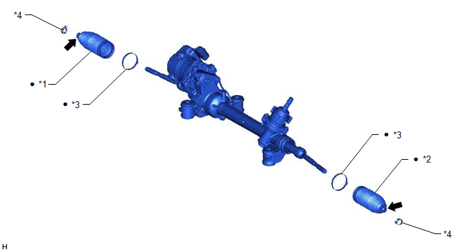
ILLUSTRATION
|
*1 | NO. 1 STEERING RACK BOOT |
*2 | NO. 2 STEERING RACK BOOT |
|
*3 | NO. 2 STEERING RACK BOOT CLAMP |
*4 | STEERING RACK BOOT CLIP |
|
● | Non-reusable part |
.png) |
Lithium soap base glycol grease |
READ NEXT:
 Removal
REMOVAL CAUTION / NOTICE / HINT
The necessary procedures (adjustment, calibration, initialization, or registration) that must be performed after parts are removed and installed, or replaced during
Disassembly
DISASSEMBLY PROCEDURE 1. REMOVE STEERING RACK BOOT CLIP (for LH Side)
(a) Using pliers, remove the steering rack boot clip. 2. REMOVE STEERING RACK BOOT CLIP (for RH Side)
HINT: Perform the same
Inspection
INSPECTION PROCEDURE 1. INSPECT TIE ROD ASSEMBLY LH
(a) Secure the tie rod assembly LH in a vise between aluminum plates.
NOTICE: Do not overtighten the vise.
(b) Instal
SEE MORE:
Data List / Active Test
DATA LIST / ACTIVE TEST DATA LIST NOTICE:
In the table below, the values listed under "Normal Condition" are reference values. Do not depend solely on these reference values when deciding whether a part is faulty or not.
HINT: Using the Techstream to read the Data List allows the values or state
Daytime Running Light Circuit
DESCRIPTION The main body ECU (multiplex network body ECU) controls the daytime running lights. WIRING DIAGRAM
for Bulb Type Turn Signal Light
for LED Type Turn Signal Light
CAUTION / NOTICE / HINT
NOTICE:
Inspect the fuses for circuits related to this system before performing th
