Toyota Camry (XV70): Disassembly
DISASSEMBLY
PROCEDURE
1. REMOVE FRONT DISC BRAKE PISTON
| (a) Place a piece of cloth between the front disc brake piston and front disc brake cylinder. |
|
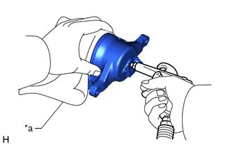
(b) Apply compressed air to remove the front disc brake piston from the front disc brake cylinder.
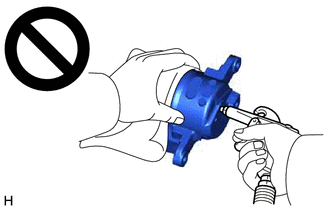
CAUTION:
- Do not hold the front disc brake cylinder with any part of your hand between the front disc brake cylinder and front disc brake piston.
- Do not place any part of your hand in front of the front disc brake piston when using compressed air as a severe injury may result.
NOTICE:
Do not allow any brake fluid to spatter.
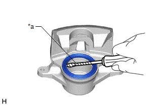
2. REMOVE CYLINDER BOOT
|
(a) Using a screwdriver with its tip wrapped with protective tape, remove the cylinder boot from the front disc brake cylinder. NOTICE: Be careful not to damage the front disc brake cylinder. |
|
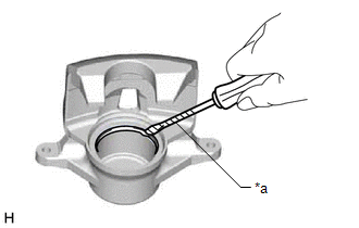
3. REMOVE PISTON SEAL
|
(a) Using a screwdriver with its tip wrapped with protective tape, remove the piston seal from the front disc brake cylinder. NOTICE: Do not damage the inner surface or piston seal groove of the front disc brake cylinder. |
|
4. REMOVE FRONT DISC BRAKE BLEEDER PLUG CAP
(a) Remove the front disc brake bleeder plug cap from the front disc brake bleeder plug.
5. REMOVE FRONT DISC BRAKE BLEEDER PLUG
(a) Remove the front disc brake bleeder plug from the front disc brake cylinder.
READ NEXT:
 Inspection
INSPECTION PROCEDURE 1. INSPECT BRAKE CYLINDER AND PISTON
(a) Check the front disc brake cylinder bore and front disc brake piston for rust and scoring. If necessary, replace the front disc brake cy
Reassembly
REASSEMBLY CAUTION / NOTICE / HINT PROCEDURE
1. TEMPORARILY TIGHTEN FRONT DISC BRAKE BLEEDER PLUG (a) Temporarily install the front disc brake bleeder plug to the front disc brake cylinder.
HINT:
Installation
INSTALLATION CAUTION / NOTICE / HINT
NOTICE:
Immediately after installing the brake pads, the braking performance may be reduced. Always perform a road test in a safe place while paying attentio
SEE MORE:
Right Rear Wheel Speed Sensor Circuit Short to Ground or Open (C051214)
DESCRIPTION Refer to DTC C051212 Click here
DTC No. Detection Item
DTC Detection Condition Trouble Area
C051214 Right Rear Wheel Speed Sensor Circuit Short to Ground or Open
A short or open circuit is detected in the speed sensor signal circuit for 0.12 seconds or
Inspection
INSPECTION PROCEDURE 1. INSPECT LUGGAGE COMPARTMENT DOOR OPENING SWITCH ASSEMBLY
(a) Check the switch. (1) Measure the resistance according to the value(s) in the table below.
Standard Resistance:
Tester Connection
Condition Specified Condition
2 - 5 Pressed
