Toyota Camry (XV70): Electric Parking Brake does not Operate
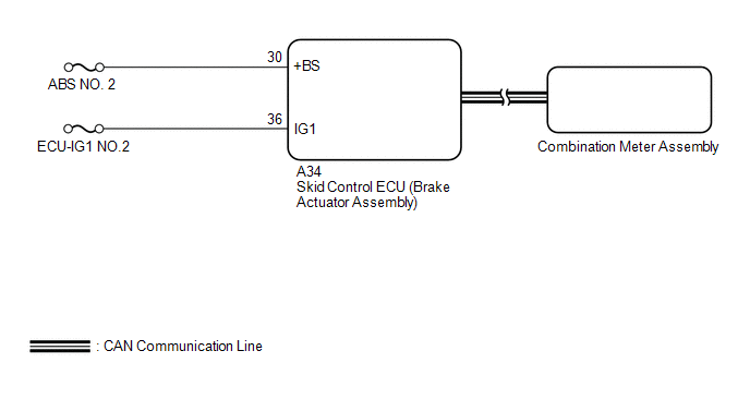
WIRING DIAGRAM
CAUTION / NOTICE / HINT
NOTICE:
Inspect the fuses for circuits related to this system before performing the following procedure.
HINT:
Even if the electric parking brake is operating normally, the parking brake indicator light on the combination meter may be malfunctioning.
PROCEDURE
| 1. |
CHECK CAN COMMUNICATION SYSTEM |
(a) Check if CAN communication system DTCs are output.
Chassis > Brake > Trouble Codes| Result |
Proceed to |
|---|---|
| DTCs are not output |
A |
| DTCs are output |
B |
| B |
.gif) | GO TO CAN COMMUNICATION SYSTEM |
|
.gif)
| 2. |
VEHICLE OPERATION CHECK |
(a) With the wheels not contacting the ground, check the condition of the rear wheels when the electric parking brake is operating and not operating.
Click here .gif)
|
Result | Proceed to |
|---|---|
|
Lock and release operation is normal and parking brake indicator light turns off or blinks |
A |
| Lock and release operation is malfunctioning and parking brake indicator light illuminates or turns off according to switch operation |
B |
| Lock and release operation is malfunctioning and parking brake indicator light turns off or blinks |
C |
| B |
| INSPECT REAR BRAKE |
| C |
| GO TO STEP 4 |
|
| 3. |
INSPECT COMBINATION METER ASSEMBLY |
(a) Perform the Active Test of the combination meter assembly using the Techstream.
Body Electrical > Combination Meter > Active Test|
Tester Display |
|---|
| Park Warning |
(b) Check the combination meter assembly.
OK:
Parking brake indicator light turns on or off in accordance with Techstream operation.
| OK | | REPLACE SKID CONTROL ECU (BRAKE ACTUATOR ASSEMBLY) |
| NG | | GO TO METER / GAUGE SYSTEM |
| 4. |
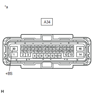
CHECK HARNESS AND CONNECTOR (+BS TERMINAL VOLTAGE) |
(a) Turn the ignition switch off.
| (b) Disconnect the A34 skid control ECU (brake actuator assembly) connector. |
|
(c) Measure the voltage according to the value(s) in the table below.
Standard Voltage:
|
Tester Connection | Condition |
Specified Condition |
|---|---|---|
|
A34-30 (+BS) - Body ground |
Ignition switch off | 11 to 14 V |
| NG | | REPAIR OR REPLACE HARNESS OR CONNECTOR |
|
| 5. |
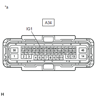
CHECK HARNESS AND CONNECTOR (IG1 TERMINAL VOLTAGE) |
(a) Turn the ignition switch off.
| (b) Disconnect the A34 skid control ECU (brake actuator assembly) connector. |
|
(c) Measure the voltage according to the value(s) in the table below.
Standard Voltage:
|
Tester Connection | Condition |
Specified Condition |
|---|---|---|
| A34-36 (IG1) - Body ground |
Ignition switch ON | 11 to 14 V |
| OK | | REPLACE SKID CONTROL ECU (BRAKE ACTUATOR ASSEMBLY) |
| NG | | REPAIR OR REPLACE HARNESS OR CONNECTOR |
READ NEXT:
 Message Not Displayed on Multi-information Display When AUTO Function Set to ON/OFF
DESCRIPTION When the AUTO function is set to ON/OFF, a message is displayed on the multi-information display in the combination meter assembly. WIRING DIAGRAM
PROCEDURE
1.
CHECK OPERATIO
Brake Warning Light (Yellow) Remains On
DESCRIPTION This procedure is for troubleshooting when the brake warning light (yellow) remains on but no DTCs are output.
The skid control ECU (brake actuator assembly) controls the brake warning l
Electric Parking Brake System AUTO Function Circuit
DESCRIPTION The skid control ECU (brake actuator assembly) receives shift position signals from the ECM via CAN communication to control the electric parking brake system AUTO function (shift-linked f
SEE MORE:
Trailer towing
Toyota does not recommend towing a trailer with your vehicle.
Toyota also does not recommend the installation of a tow hitch
or the use of a tow hitch carrier for a wheelchair, scooter, bicycle,
etc. Your vehicle is not designed for trailer towing or for the
use of tow hitch mounted carriers.
Fuel Rail Pressure Sensor "A" Circuit Short to Battery or Open (P019015)
DESCRIPTION Refer to DTC P019011. Click here
DTC No. Detection Item
DTC Detection Condition Trouble Area
MIL Memory
Note P019015
Fuel Rail Pressure Sensor "A" Circuit Short to Battery or Open
The fuel pressure sensor (for high pressure side) output volt
