Toyota Camry (XV70): Front Side Marker Light Bulb
Components
COMPONENTS
ILLUSTRATION
|
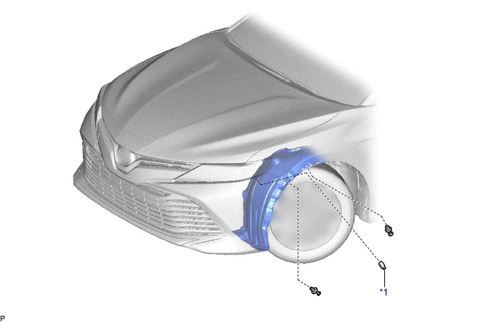
*1 | FRONT SIDE MARKER LIGHT BULB |
- | - |
Removal
REMOVAL
CAUTION / NOTICE / HINT
HINT:
- Use the same procedure for the RH side and LH side.
- The following procedure is for the LH side.
PROCEDURE
1. REMOVE FRONT SIDE MARKER LIGHT BULB
(a) Turn the steering wheel fully to the right.
HINT:
When removing the fog light assembly RH, turn the steering wheel to the left.
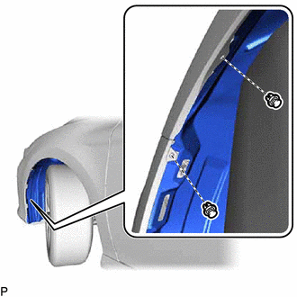
| (b) Remove the 2 clips. |
|
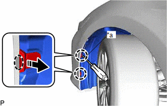
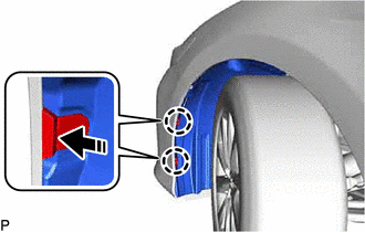
(c) Using a screwdriver with its tip wrapped with protective tape, disengage the 2 claws and separate the front fender splash shield sub-assembly as shown in the illustration.
|
*a | Protective Tape |
.png) |
Insert Screwdriver Here |
.png) |
Remove in this Direction |
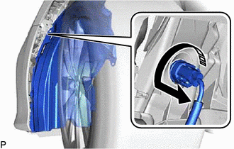
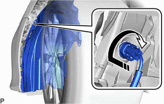
(d) Turn the headlight cord with the front side marker light bulb as shown in the illustration to disconnect them as a unit.
|
|
Remove in this Direction |
(e) Remove the front side marker light bulb from the headlight cord.
Installation
INSTALLATION
CAUTION / NOTICE / HINT
HINT:
- Use the same procedure for the RH side and LH side.
- The following procedure is for the LH side.
PROCEDURE
1. INSTALL FRONT SIDE MARKER LIGHT BULB
(a) Install the front side marker light bulb to the headlight cord.
(b) Turn the headlight cord with the front side marker light bulb as shown in the illustration to connect them as a unit.
.png) |
Install in this Direction |
(c) Engage the 2 claws as shown in the illustration.
|
|
Install in this Direction |
(d) Install the front fender splash shield sub-assembly with the 2 clips.
(e) Turn the steering wheel to its original position.
READ NEXT:
 Front Turn Signal Light Bulb
ComponentsCOMPONENTS ILLUSTRATION
*1 FRONT TURN SIGNAL LIGHT BULB
- - RemovalREMOVAL CAUTION / NOTICE / HINT
HINT:
Use the same procedure for the RH side and LH side.
Front Wiper Rubber
ComponentsCOMPONENTS ILLUSTRATION
*1 FRONT WIPER BLADE
*2 WIPER RUBBER
*3 FRONT WIPER RUBBER BACKING PLATE
- - RemovalREMOVAL CAUTION / NOTICE / HINT
NOTICE:
SEE MORE:
VEHICLE CONTROL HISTORY (RoB)
VEHICLE CONTROL HISTORY (RoB) DESCRIPTION
Vehicle Control History (RoB) is a function that captures and stores ECU data when triggered by specific vehicle behavior.
It may be possible to determine the cause of the malfunction by checking the vehicle history information and freeze frame dat
Removal
REMOVAL CAUTION / NOTICE / HINT
The necessary procedures (adjustment, calibration, initialization, or registration) that must be performed after parts are removed and installed, or replaced during front stabilizer bar removal/installation are shown below. Necessary Procedures After Parts Removed/I
