Toyota Camry (XV70): Inspection
INSPECTION
PROCEDURE
1. INSPECT WATER INLET WITH THERMOSTAT SUB-ASSEMBLY
(a) Check the valve opening.
HINT:
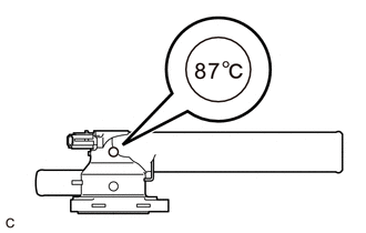
The valve opening temperature is inscribed on the water inlet with thermostat sub-assembly.
| (1) Add 15 cc (0.9 cu. in.) of water to the water inlet with thermostat sub-assembly from the inlet pipe side. |
|
(2) Confirm that water does not flow out from the valve side of the water inlet with thermostat sub-assembly.
If water flows out from the valve side of the water inlet with thermostat sub-assembly, replace the water inlet with thermostat sub-assembly with a new one.
(3) Immerse the water inlet with thermostat sub-assembly in water that is between 92°C (198°F) and 96°C (205°F) for 5 minutes or more.
NOTICE:
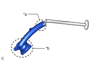
- Do not allow any water to come into contact with the connector of the water inlet with thermostat sub-assembly.
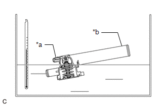
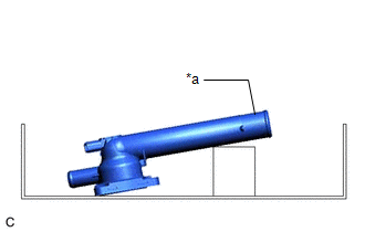
- Make sure that the end of the inlet pipe of the water inlet with thermostat sub-assembly is not facing downward.
- Make sure to immerse the water inlet with thermostat sub-assembly in the water as shown in the illustration.
|
*a | Connector |
|
*b | Inlet Pipe |
 |
Temperature Sensor |
| (4) Leave the water inlet with thermostat sub-assembly at ambient temperature for 5 minutes so that the valve closes. NOTICE: Make sure that the end of the inlet pipe of the water inlet with thermostat sub-assembly is not facing downward. |
|
(5) Check that the water that was added to the water inlet with thermostat sub-assembly has completely flowed out.
If the water that was added to the water inlet with thermostat sub-assembly has not completely flowed out, replace the water inlet with thermostat sub-assembly with a new one.
(b) Check the resistance of the temperature sensor.
(1) Measure the resistance according to the value(s) in the table below.
Standard Resistance:
|
Tester Connection | Condition |
Specified Condition |
|---|---|---|
|
1 - 2 | Always |
10.6 to 14.2 Ω |
If the result is not as specified, replace the water inlet with thermostat sub-assembly.
READ NEXT:
 Installation
INSTALLATION PROCEDURE 1. INSTALL WATER INLET WITH THERMOSTAT SUB-ASSEMBLY
(a) Install a new gasket to the water inlet with thermostat sub-assembly.
(b) Install the water inlet with thermostat sub
Components
COMPONENTS ILLUSTRATION
*1 ENGINE WATER PUMP ASSEMBLY
*2 NO. 2 IDLER PULLEY SUB-ASSEMBLY
*3 WATER PUMP PULLEY
*4 WATER PUMP GASKET
*5 V-RIBBED BELT
SEE MORE:
Components
COMPONENTS ILLUSTRATION
*1 BATTERY CLAMP SUB-ASSEMBLY
- -
N*m (kgf*cm, ft.*lbf): Specified torque
- - ILLUSTRATION
*1 TRANSMISSION CONTROL CABLE ASSEMBLY
*2 TRANSMISSION CONTROL SHAFT LEVER
*3 PARK/NEUTRAL POSITION SWITCH AS
DCM Communication Stop Mode
DESCRIPTION
Detection Item Symptom
Trouble Area DCM Communication Stop Mode
Any of the following conditions are met:
Communication stop for "DCM" is indicated on the "Communication Bus Check" screen of the Techstream.
Click here
Communication stop
