Toyota Camry (XV70): Inspection
INSPECTION
PROCEDURE
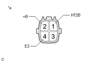
1. INSPECT HEATED OXYGEN SENSOR (for Bank 1)
| (a) Measure the resistance according to the value(s) in the table below. Standard Resistance:
If the result is not as specified, replace the heated oxygen sensor. |
|

2. INSPECT HEATED OXYGEN SENSOR (for Bank 2)
| (a) Measure the resistance according to the value(s) in the table below. Standard Resistance:
If the result is not as specified, replace the heated oxygen sensor. |
|
READ NEXT:
 Installation
INSTALLATION PROCEDURE 1. INSTALL HEATED OXYGEN SENSOR (for Bank 2)
HINT: Perform "Inspection After Repair" after replacing the heated oxygen sensor.
Click here
(a) Using SST, install
Components
COMPONENTS ILLUSTRATION
*1 IGNITION COIL ASSEMBLY
*2 SPARK PLUG
*3 V-BANK COVER SUB-ASSEMBLY
*4 VACUUM HOSE
N*m (kgf*cm, ft.*lbf): Specified torque
SEE MORE:
Data List / Active Test
DATA LIST / ACTIVE TEST DATA LIST HINT:
Using the Techstream to read the Data List allows the values or states of switches, sensors, actuators and other items to be read without removing any parts. This non-intrusive inspection can be very useful because intermittent conditions or signals may be
Cruise Control System Internal Failure (P057504,P057549)
DESCRIPTION When the ECM detects an internal malfunction, DTC P057504 or P057549 is stored.
DTC No. Detection Item
DTC Detection Condition Trouble Area
DTC Output from
P057504 Cruise Control System Internal Failure
When the dynamic radar cruise control system is o
