Toyota Camry (XV70): Components
COMPONENTS
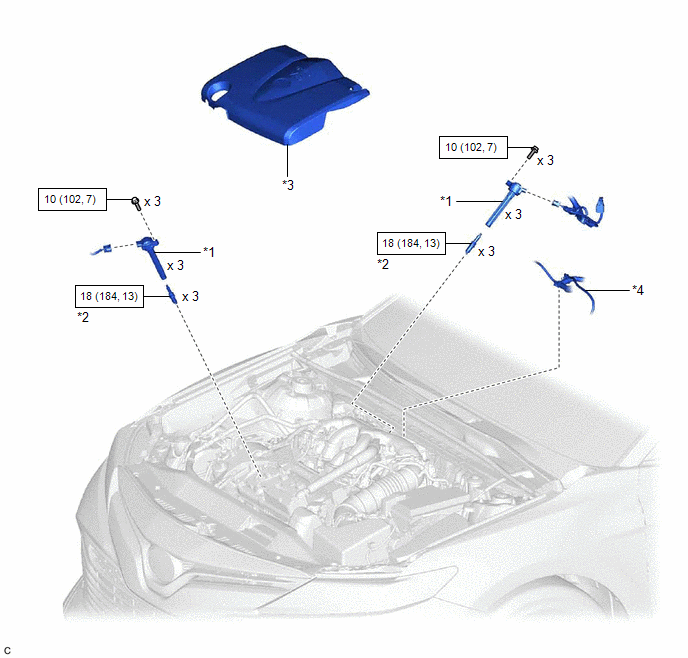
ILLUSTRATION
|
*1 | IGNITION COIL ASSEMBLY |
*2 | SPARK PLUG |
|
*3 | V-BANK COVER SUB-ASSEMBLY |
*4 | VACUUM HOSE |
.png) |
N*m (kgf*cm, ft.*lbf): Specified torque |
- | - |
READ NEXT:
 Removal
REMOVAL CAUTION / NOTICE / HINT
The necessary procedures (adjustment, calibration, initialization, or registration) that must be performed after parts are removed and installed, or replaced during i
Installation
INSTALLATION PROCEDURE 1. INSTALL SPARK PLUG
Click here 2. INSTALL IGNITION COIL ASSEMBLY
HINT: Perform "Inspection After Repair" after replacing an ignition coil assembly.
Click here
SEE MORE:
Installation
INSTALLATION CAUTION / NOTICE / HINT
NOTICE:
Do not remove/install the spiral cable with sensor sub-assembly with the battery connected and the ignition switch ON.
Do not rotate the spiral cable with sensor sub-assembly without the steering wheel assembly installed, with the battery
System Description
SYSTEM DESCRIPTION POWER MIRROR CONTROL SYSTEM DESCRIPTION
(a) This system has the following functions: electrical remote control mirror function and mirror heater function.
FUNCTION OF MAIN COMPONENT
Component Function
Outer rear view mirror assembly
Vertical mirror m
© 2023-2026 Copyright www.tocamry.com
