Toyota Camry (XV70): Installation
INSTALLATION
PROCEDURE
1. INSTALL HEATED OXYGEN SENSOR (for Bank 2)
HINT:
Perform "Inspection After Repair" after replacing the heated oxygen sensor.
Click here .gif)
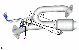
| (a) Using SST, install the heated oxygen sensor to the front exhaust pipe assembly. SST: 09224-00012 Torque: Specified tightening torque : 44 N·m {449 kgf·cm, 32 ft·lbf} NOTICE: If the heated oxygen sensor has been struck or dropped, replace it. HINT:
|
|
2. INSTALL FRONT EXHAUST PIPE ASSEMBLY
Click here
3. INSTALL NO. 1 EXHAUST PIPE SUPPORT BRACKET (for Lower Side)
Click here
4. INSTALL BODY MOUNTING PLATE
Click here
5. INSTALL FRONT FLOOR COVER LH
Click here
6. INSTALL FRONT FLOOR COVER RH
Click here
7. INSTALL HEATED OXYGEN SENSOR (for Bank 1)
HINT:
Perform "Inspection After Repair" after replacing the heated oxygen sensor.
Click here
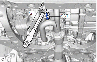
| (a) Using SST, install the heated oxygen sensor to the front exhaust pipe assembly. SST: 09224-00012 Torque: Specified tightening torque : 44 N·m {449 kgf·cm, 32 ft·lbf} NOTICE: If the heated oxygen sensor has been struck or dropped, replace it. HINT:
|
|
(b) Engage the wire harness clamp.
(c) Connect the heated oxygen sensor connector.
8. INSPECT FOR EXHAUST GAS LEAK
Click here
9. INSTALL REAR ENGINE UNDER COVER RH
Click here
10. INSTALL NO. 1 ENGINE UNDER COVER
Click here
11. INSTALL FRONT WHEEL OPENING EXTENSION PAD LH
Click here
12. INSTALL FRONT WHEEL OPENING EXTENSION PAD RH
Click here
13. PERFORM INITIALIZATION
(a) Perform "Inspection After Repair" after replacing the heated oxygen sensor.
Click here
READ NEXT:
 Components
COMPONENTS ILLUSTRATION
*1 IGNITION COIL ASSEMBLY
*2 SPARK PLUG
*3 V-BANK COVER SUB-ASSEMBLY
*4 VACUUM HOSE
N*m (kgf*cm, ft.*lbf): Specified torque
Removal
REMOVAL CAUTION / NOTICE / HINT
The necessary procedures (adjustment, calibration, initialization, or registration) that must be performed after parts are removed and installed, or replaced during i
SEE MORE:
Right Front Wheel Speed Sensor Internal Electronic Failure (C050649)
DESCRIPTION When the system is starting up and the skid control ECU (brake actuator assembly) detects a speed sensor circuit malfunction via the speed sensor circuit self-diagnosis function, this DTC is stored.
DTC No. Detection Item
DTC Detection Condition Trouble Area
C05064
Microphone Circuit
DESCRIPTION
w/o Manual (SOS) Switch:
The radio and display receiver assembly, roof console box sub-assembly and telephone microphone assembly are connected to each other using the microphone connection detection signal lines.
Using this circuit, the radio and display receiver assembly sends
