Toyota Camry (XV70): Reassembly
REASSEMBLY
PROCEDURE
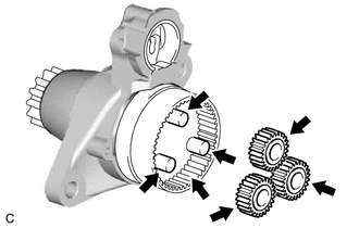
1. INSTALL PLANETARY GEAR
(a) Apply high-temperature grease to the 3 planetary gears, 3 planetary gear shafts and repair service starter kit.
.png) |
High-temperature Grease |
(b) Install the 3 planetary gears to the repair service starter kit.
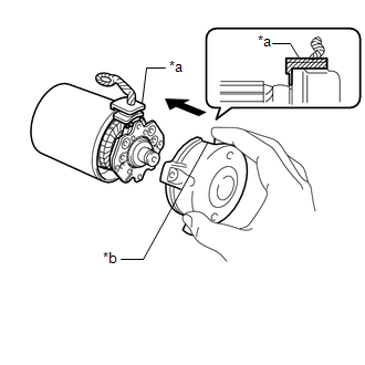
2. INSTALL STARTER ARMATURE ASSEMBLY
(a) Install the starter armature assembly to the starter yoke assembly.
NOTICE:
The magnet of the starter yoke assembly may attract the starter armature assembly when the starter commutator end frame assembly is installed, causing the magnet to break.
3. INSTALL STARTER BRUSH HOLDER ASSEMBLY
| (a) Hold the brush spring back and set the 4 brushes as shown in the illustration. |
|
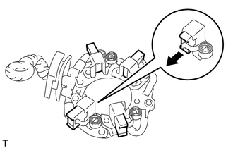
| (b) Install the starter brush holder assembly to the starter armature assembly and push in the 4 brushes as shown in the illustration. |
|
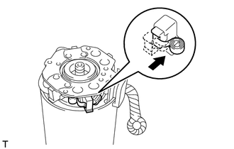
| (c) Fit the protrusion of the grommet between the negative (-) brush holder plate and positive (+) motor lead wire. |
|
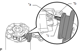
4. INSTALL STARTER COMMUTATOR END FRAME ASSEMBLY
| (a) Install the starter commutator end frame assembly to the starter yoke assembly. NOTICE: Align the field coil lead wire rubber of the starter yoke assembly with the cutout of the starter commutator end frame assembly. |
|
(b) Install the 2 screws.
Torque:
1.5 N·m {15 kgf·cm, 13 in·lbf}
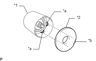
5. INSTALL STARTER ARMATURE PLATE
| (a) Align the starter armature plate so that the protrusion fits between the stoppers of the starter yoke assembly, and install the starter armature plate. NOTICE: Make sure the protrusion of the starter armature plate is inserted between the stoppers of the starter yoke assembly. |
|
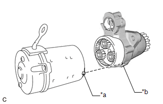
6. INSTALL STARTER YOKE ASSEMBLY
| (a) Align the protrusion of the starter yoke assembly with the cutout of the repair service starter kit. |
|
(b) Using a T25 "TORX" socket wrench, install the starter yoke assembly with the 2 through bolts.
Torque:
6.0 N·m {61 kgf·cm, 53 in·lbf}
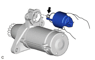
7. INSTALL MAGNET STARTER SWITCH ASSEMBLY
(a) Apply high-temperature grease to the plunger as shown in the illustration.
|
|
High-temperature Grease |
(b) Hang the hook of the magnet starter switch assembly on the pinion drive lever.
(c) Install the magnet starter switch assembly with the 2 nuts.
Torque:
7.5 N·m {76 kgf·cm, 66 in·lbf}
(d) Connect the field coil lead wire to the magnet starter switch assembly with the nut.
Torque:
10 N·m {102 kgf·cm, 7 ft·lbf}
READ NEXT:
 Installation
INSTALLATION PROCEDURE 1. INSTALL STARTER ASSEMBLY
(a) Install the starter assembly with the 2 bolts. Torque: 46 N·m {469 kgf·cm, 34 ft·lbf}
(b) Connect the engine wire to the terminal 30 with
Components
COMPONENTS ILLUSTRATION
*1 AIR CLEANER ASSEMBLY WITH AIR CLEANER HOSE
*2 INLET AIR CLEANER ASSEMBLY
*3 BATTERY CLAMP SUB-ASSEMBLY
*4 COOL AIR INTAKE DUCT SEAL
Removal
REMOVAL CAUTION / NOTICE / HINT
The necessary procedures (adjustment, calibration, initialization or registration) that must be performed after parts are removed and installed, or replaced starter a
SEE MORE:
Installation
INSTALLATION PROCEDURE 1. INSTALL FUEL PIPE PLUG SUB-ASSEMBLY
(a) Install a new O-ring, No. 1 fuel injector back-up ring, No. 2 fuel injector back-up ring and No. 3 fuel injector back-up ring to the fuel pipe plug sub-assembly as shown in the illustration.
*1 Fuel Pipe Plug Sub-assemb
Removal
REMOVAL CAUTION / NOTICE / HINT
The necessary procedures (adjustment, calibration, initialization, or registration) that must be performed after parts are removed and installed, or replaced during rear suspension member sub-assembly removal/installation are shown below. Necessary Procedures After
