Toyota Camry (XV70): Inspection
INSPECTION
PROCEDURE
1. INSPECT ENGINE OIL PRESSURE SWITCH ASSEMBLY
| (a) Disengage the clamp to disconnect the wire harness protector. |
|
.png)
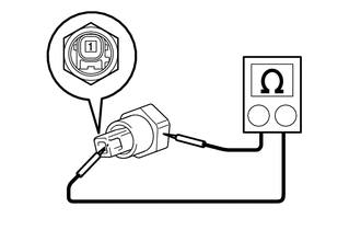
(b) Disconnect the engine oil pressure switch assembly connector.
(c) Start the engine.
| (d) Measure the resistance according to the value(s) in the table below. Standard Resistance:
If the result is not as specified, replace the engine oil pressure switch assembly. |
|
(e) Connect the engine oil pressure switch assembly connector.
(f) Connect the wire harness protector.
READ NEXT:
 Installation
INSTALLATION PROCEDURE 1. INSTALL ENGINE OIL PRESSURE SWITCH ASSEMBLY
(a) Apply adhesive to 2 or 3 threads of the engine oil pressure switch assembly.
Adhesive: Toyota Genuine Adhesive 1344,
Components
COMPONENTS ILLUSTRATION
*1 ENGINE OIL PRESSURE SWITCH ASSEMBLY
*2 FRONT FENDER APRON SEAL RH
*3 WIRE HARNESS PROTECTOR
- -
N*m (kgf*cm, ft*lbf): Sp
Removal
REMOVAL PROCEDURE 1. REMOVE FRONT FENDER APRON SEAL RH
Click here
2. DRAIN ENGINE OIL Click here
3. REMOVE ENGINE OIL PRESSURE SWITCH ASSEMBLY
(a) Disengage the clamp to disco
SEE MORE:
Parts Location
PARTS LOCATION ILLUSTRATION
*1 INNER REAR VIEW MIRROR ASSEMBLY
- GARAGE DOOR OPENER *2
INSTRUMENT PANEL JUNCTION BLOCK ASSEMBLY - ECU-DCC NO. 2 FUSE
- ECU-IG1 NO. 3 FUSE
Removal
REMOVAL CAUTION / NOTICE / HINT
The necessary procedures (adjustment, calibration, initialization, or registration) that must be performed after parts are removed and installed, or replaced during outer rear view mirror assembly with cover removal/installation are shown below. Necessary Procedure
© 2023-2026 Copyright www.tocamry.com
