Toyota Camry (XV70): Inspection
INSPECTION
PROCEDURE
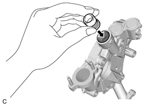
1. INSPECT OIL PUMP RELIEF VALVE
| (a) Coat the oil pump relief valve with engine oil and check that it falls smoothly into the valve hole by its own weight. HINT: If the oil pump relief valve does not fall smoothly, replace the timing chain cover assembly. |
|
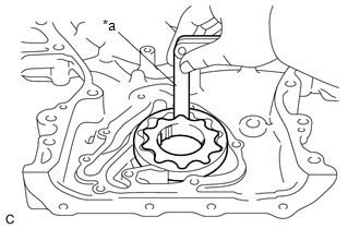
2. INSPECT OIL PUMP ROTOR SET
(a) Apply engine oil to the drive rotor and driven rotor.
| (b) Install the drive rotor and driven rotor to the timing chain cover assembly with the rotor marks facing up. Check that the rotors rotate smoothly. HINT: If the rotors do not rotate smoothly, replace the timing chain cover assembly. |
|

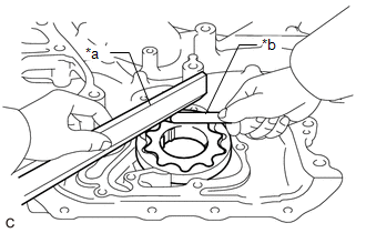
| (c) Check the tip clearance. (1) Using a feeler gauge, measure the clearance between the drive rotor and driven rotor tips as shown in the illustration. Standard Tip Clearance: 0.040 to 0.150 mm (0.00157 to 0.00591 in.) Maximum Tip Clearance: 0.150 mm (0.00591 in.) HINT: If the tip clearance is more than the maximum, replace the timing chain cover assembly. |
|
| (d) Check the side clearance. (1) Using a feeler gauge and precision straightedge, measure the clearance between the drive rotor and driven rotor and precision straightedge as shown in the illustration. Standard Side Clearance: 0.030 to 0.070 mm (0.00118 to 0.00276 in.) Maximum Side Clearance: 0.070 mm (0.00276 in.) HINT: If the side clearance is more than the maximum, replace the timing chain cover assembly. |
|
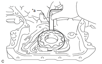
| (e) Check the body clearance. (1) Using a feeler gauge, measure the clearance between the timing chain cover assembly and driven rotor as shown in the illustration. Standard Body Clearance: 0.250 to 0.325 mm (0.00984 to 0.0128 in.) Maximum Body Clearance: 0.325 mm (0.0128 in.) HINT: If the body clearance is more than the maximum, replace the timing chain cover assembly. |
|
READ NEXT:
 Reassembly
REASSEMBLY PROCEDURE 1. INSTALL OIL PUMP ROTOR SET
(a) Coat the drive rotor and driven rotor with engine oil and place them into the timing chain cover assembly with the rotor marks facing up. C
Installation
INSTALLATION PROCEDURE 1. INSTALL TIMING CHAIN COVER ASSEMBLY
(a) Clean the contact surfaces of the engine assembly, and confirm that no oil, moisture, or other foreign matter is on the surfaces.
Components
COMPONENTS ILLUSTRATION
*A w/ Stud Bolt
*B w/o Stud Bolt
*1 TIMING CHAIN CASE OIL SEAL
*2 TIMING CHAIN COVER ASSEMBLY
*3 OIL PUMP GASKET
- -
SEE MORE:
On-vehicle Inspection
ON-VEHICLE INSPECTION PROCEDURE
1. INSPECT BRAKE FLUID LEVEL IN RESERVOIR
(a) Check the fluid level. If the brake fluid level is lower than the MIN line, inspect for brake fluid leaks and brake pad wear. If necessary, refill the reservoir with brake fluid to the MAX line after repair or repl
Initialization
INITIALIZATION Inspection After Repair Perform Learning Value Reset and Idle Learning after replacing or servicing parts related to engine operation. Details on procedures required are indicated by an asterisk and a number, and are explained in detail following the table.
Part Replaced Engin
