Toyota Camry (XV70): Inspection
INSPECTION
PROCEDURE
1. INSPECT REAR LIGHT ASSEMBLY LH (for TMMK Made LED Type Back-up Light)
|
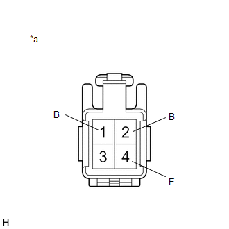
*a | Component without harness connected (Rear Light Assembly LH) |
(a) Apply battery voltage to the rear light assembly LH and check that the lights illuminate.
OK:
|
Condition | Specified Condition |
|---|---|
|
Battery positive (+) → Terminal 1 (B) Battery negative (-) → Terminal 4 (E) |
Taillight illuminates |
|
Battery positive (+) → Terminal 2 (B) Battery negative (-) → Terminal 4 (E) |
Back-up light illuminates |
If the result is not as specified, replace the rear light assembly LH.
2. INSPECT REAR LIGHT ASSEMBLY RH (for TMMK Made LED Type Back-up Light)
|
*a | Component without harness connected (Rear Light Assembly RH) |
(a) Apply battery voltage to the rear light assembly RH and check that the lights illuminate.
OK:
|
Condition | Specified Condition |
|---|---|
|
Battery positive (+) → Terminal 1 (B) Battery negative (-) → Terminal 4 (E) |
Taillight illuminates |
|
Battery positive (+) → Terminal 2 (B) Battery negative (-) → Terminal 4 (E) |
Back-up light illuminates |
If the result is not as specified, replace the rear light assembly RH.
READ NEXT:
 Reassembly
REASSEMBLY CAUTION / NOTICE / HINT
HINT:
Use the same procedure for the RH side and LH side.
The following procedure is for the LH side.
PROCEDURE 1. INSTALL REAR LIGHT LENS AND BOD
Installation
INSTALLATION CAUTION / NOTICE / HINT
HINT:
Use the same procedure for the RH side and LH side.
The following procedure is for the LH side.
PROCEDURE 1. INSTALL REAR LIGHT ASSEMBLY
Rear Side Marker Light Bulb
ReplacementREPLACEMENT CAUTION / NOTICE / HINT
HINT:
Use the same procedure for the RH side and LH side.
The following procedure is for the LH side.
PROCEDURE 1. REMOVE REAR COMBINA
SEE MORE:
Freeze Frame Data
FREEZE FRAME DATA FREEZE FRAME DATA (a) When a DTC is stored, the 4WD ECU assembly stores the current vehicle state as Freeze Frame Data.
HINT: Freeze Frame Data at the time a DTC is stored:
When the 4WD ECU assembly stores data at the time a DTC is stored, no updates will be performed until
Engine compartment
2.5 L 4-cylinder (A25A-FKS) engine
Fuse boxes (if equipped)
Engine oil filler cap
Engine oil level dipstick
Brake fluid reservoir
Battery
Radiator
Electric cooling fan
Condenser
Engine coolant reservoir
Washer fluid tank
3.5 L V6 (2GR-FKS) engine
Fuse boxes (if equip
