Toyota Camry (XV70): Installation
INSTALLATION
PROCEDURE
1. INSTALL FUEL INJECTOR ASSEMBLY
HINT:
Perform "Inspection After Repair" after replacing a fuel injector assembly.
Click here .gif)
(a) Apply a light coat of spindle oil or gasoline to 6 new O-rings, and install one to each fuel injector assembly.
NOTICE:
Check that there is no damage or foreign matter on the groove of the fuel injector assembly when installing the O-ring to each fuel injector assembly.
(b) for Bank 1:
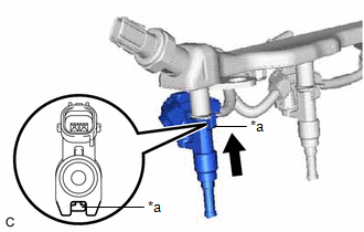
(1) Connect the 3 fuel injector assembly connectors.
| (2) Install the 3 fuel injector assemblies to the fuel delivery pipe with sensor assembly. NOTICE:
|
|
(3) Engage the clamp to connect the No. 5 engine wire to the fuel delivery pipe with sensor assembly.
(c) for Bank 2:
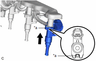
(1) Connect the 3 fuel injector assembly connectors.
| (2) Install the 3 fuel injector assemblies to the fuel delivery pipe with sensor assembly. NOTICE:
|
|
(3) Engage the clamp to connect the No. 5 engine wire to the fuel delivery pipe with sensor assembly.
2. INSTALL INJECTOR VIBRATION INSULATOR
(a) Install 6 new injector vibration insulators to the intake manifold.
3. INSTALL NO. 1 DELIVERY PIPE SPACER
(a) Install the 4 No. 1 delivery pipe spacers to the intake manifold.
4. INSTALL FUEL DELIVERY PIPE WITH SENSOR ASSEMBLY
(a) Place the fuel delivery pipe with sensor assembly with the 6 fuel injector assemblies onto the intake manifold.
NOTICE:
Be careful not to drop the fuel injector assemblies when installing the fuel delivery pipe with sensor assembly.
(b) Install the fuel delivery pipe with sensor assembly with the fuel injector assemblies with the 4 bolts.
Torque:
17 N·m {173 kgf·cm, 13 ft·lbf}
(c) Connect the 2 No. 5 engine wire connectors.
(d) Connect the fuel pressure sensor connector.
5. CONNECT FUEL TUBE SUB-ASSEMBLY
(a) Connect the fuel tube sub-assembly to the fuel delivery pipe with sensor assembly.
Click here
6. INSTALL INTAKE AIR SURGE TANK ASSEMBLY
Click here
7. CONNECT CABLE TO NEGATIVE BATTERY TERMINAL
NOTICE:
When disconnecting the cable, some systems need to be initialized after the cable is reconnected.
Click here
8. INSPECT FOR FUEL LEAK
Click here
9. PERFORM INITIALIZATION
(a) Perform "Inspection After Repair" after replacing a fuel injector assembly.
Click here
READ NEXT:
 Components
COMPONENTS ILLUSTRATION
*1 FUEL PUMP
*2 FUEL SUCTION PLATE SUB-ASSEMBLY
*3 FUEL SENDER GAUGE ASSEMBLY
*4 FUEL FILTER
*5 FUEL MAIN VALVE ASSEMBLY (for Lo
Removal
REMOVAL CAUTION / NOTICE / HINT
The necessary procedures (adjustment, calibration, initialization or registration) that must be performed after parts are removed and installed, or replaced during fu
SEE MORE:
Rear Door Opening Trim Weatherstrip
ComponentsCOMPONENTS ILLUSTRATION
*1 REAR DOOR OPENING TRIM WEATHERSTRIP
*2 REAR DOOR SCUFF PLATE RemovalREMOVAL CAUTION / NOTICE / HINT
HINT:
Use the same procedure for the RH side and LH side.
The following procedure is for the LH side.
PROCEDURE 1. RE
Check For Intermittent Problems
CHECK FOR INTERMITTENT PROBLEMS CHECK FOR INTERMITTENT PROBLEMS
HINT: A momentary interruption (open circuit) in the connectors and/or wire harness between the sensors and ECUs can be detected using the Data List function of the Techstream.
(a) Turn the ignition switch off. (b) Connect the Techs
