Toyota Camry (XV70): Installation
INSTALLATION
PROCEDURE
1. INSTALL FLOW SHUTTING VALVE (NO. 1 WATER BY-PASS HOSE)
(a) Install the flow shutting valve (No. 1 water by-pass hose) with the bolt.
Torque:
19 N·m {194 kgf·cm, 14 ft·lbf}
(b) Connect the flow shutting valve connector.
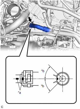
(c) Connect the flow shutting valve (No. 1 water by-pass hose) to the transmission oil cooler and slide the clip to secure it.

|
*a | 2 to 7 mm (0.0787 to 0.276 in.) |
*b | Paint Mark |
|
*c | 45° (Tabs of Clip Installation Area) |
- | - |
NOTICE:
- Make sure to slide the flow shutting valve (No. 1 water by-pass hose) until it contacts the hose stopper of the transmission oil cooler.
- Make sure to align the paint mark of the flow shutting valve (No. 1 water by-pass hose) with the paint mark of the transmission oil cooler.
- Make sure that the tabs of the clip are within the area shown in the illustration.
| (d) Connect the flow shutting valve (No. 1 water by-pass hose) to the water outlet and slide the clip to secure it. NOTICE:
|
|
(e) Engage the 2 clamps to connect the flow shutting valve (No. 1 water by-pass hose) and transmission breather hose to the hose clamp.
(f) Engage the 3 clamps to install the hose clamp.
(g) Engage the 3 clamps to install the transmission breather clamp.
2. INSTALL BATTERY CLAMP SUB-ASSEMBLY
Click here
.gif)
3. INSTALL BATTERY
Click here
4. INSTALL ECM
Click here
5. ADD ENGINE COOLANT
Click here
6. INSPECT FOR COOLANT LEAK
Click here
7. INSTALL FRONT FENDER APRON SEAL LH
Click here
8. INSTALL NO. 2 ENGINE UNDER COVER ASSEMBLY
Click here
9. INSTALL NO. 1 ENGINE UNDER COVER
Click here
10. INSTALL FRONT WHEEL OPENING EXTENSION PAD LH
Click here
11. INSTALL FRONT WHEEL OPENING EXTENSION PAD RH
Click here
12. INSTALL FRONT WHEEL LH
Click here
READ NEXT:
 Components
COMPONENTS ILLUSTRATION
*A for TMC made
- -
*1 NO. 1 ENGINE UNDER COVER
*2 NO. 2 ENGINE UNDER COVER ASSEMBLY
*3 FRONT WHEEL OPENING EXTENSION PAD LH
Removal
REMOVAL CAUTION / NOTICE / HINT
The necessary procedures (adjustment, calibration, initialization or registration) that must be performed after parts are removed and installed, or replaced during fl
Inspection
INSPECTION PROCEDURE 1. INSPECT FLOW SHUTTING VALVE (NO. 1 WATER BY-PASS HOSE)
(a) Measure the resistance according to the value(s) in the table below.
Standard Resistance:
Tester Con
SEE MORE:
Inspection
INSPECTION PROCEDURE 1. INSPECT FRONT SHOCK ABSORBER ASSEMBLY
(a) Compress and extend the front shock absorber assembly rod 4 times or more.
Standard: When compressed and extended at a constant speed, the stroke of the shock absorber rod is smooth with no abnormal resistance or sounds. When ext
Components
COMPONENTS ILLUSTRATION
*1 AIR CLEANER ASSEMBLY WITH AIR CLEANER HOSE
*2 COOL AIR INTAKE DUCT SEAL
*3 ECM
*4 INLET AIR CLEANER ASSEMBLY
*5 NO. 1 ECM BRACKET
*6 NO. 2 ECM BRACKET
*7 VACUUM HOSE
*8 NO. 1 FUEL VAPOR FEED HOSE
