Toyota Camry (XV70): Lost Communication with Wiper ECU LIN (B1245)
DESCRIPTION
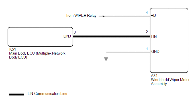
The main body ECU (multiplex network body ECU) and windshield wiper motor assembly communicate via LIN communication. The main body ECU (multiplex network body ECU) stores this DTC if communication becomes abnormal.
|
DTC No. | Detection Item |
DTC Detection Condition |
Trouble Area | Memory |
DTC Output from |
|---|---|---|---|---|---|
|
B1245 | Lost Communication with Wiper ECU LIN | Detection condition:
|
| ○ |
Main Body |
WIRING DIAGRAM
CAUTION / NOTICE / HINT
NOTICE:
Before replacing the main body ECU (multiplex network body ECU), refer to Registration.*
Click here .gif)
- *: w/ Smart Key System
PROCEDURE
|
1. | CHECK FOR DTC |
(a) Connect the Techstream to the DLC3.
(b) Turn the ignition switch to ON.
(c) Turn the Techstream on.
(d) Enter the following menus: Body Electrical / Main Body / Trouble Codes.
(e) Check for DTCs.
Body Electrical > Main Body > Trouble Codes|
Result | Proceed to |
|---|---|
|
Only DTC B1245 is output |
A |
| DTC B1245 and B1373 are output |
B |
| B | .gif) |
GO TO B1373 |
|
.gif)
|
2. | CHECK HARNESS AND CONNECTOR (MAIN BODY ECU (MULTIPLEX NETWORK BODY ECU) - WINDSHIELD WIPER MOTOR ASSEMBLY) |
(a) Disconnect the K51 main body ECU (multiplex network body ECU) connector.
(b) Disconnect the A31 windshield wiper motor assembly connector.
(c) Measure the resistance according to the value(s) in the table below.
Standard Resistance:
|
Tester Connection | Condition |
Specified Condition |
|---|---|---|
|
K51-3 (LIN3) - A31-2 (LIN) |
Always | Below 1 Ω |
| NG | |
REPAIR OR REPLACE HARNESS OR CONNECTOR |
|
|
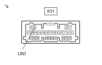
3. | CHECK MAIN BODY ECU (MULTIPLEX NETWORK BODY ECU) |
|
*a | Component without harness connected (Main Body ECU (Multiplex Network Body ECU) |
(a) Check for pulses according to the value(s) in the table below.
Standard Voltage:
|
Tester Connection | Condition |
Specified Condition |
|---|---|---|
|
K51-3 (LIN3) - Body ground |
Ignition switch off |
Below 1 V |
|
Ignition switch ON |
Pulse generation |
| NG | |
REPLACE MAIN BODY ECU (MULTIPLEX NETWORK BODY ECU)
|
|
|
4. | CHECK HARNESS AND CONNECTOR (POWER SOURCE - WINDSHIELD WIPER MOTOR ASSEMBLY) |
(a) Measure the voltage according to the value(s) in the table below.
Standard Voltage:
|
Tester Connection | Condition |
Specified Condition |
|---|---|---|
|
A31-4 (+B) - Body ground |
Ignition switch ON |
11 to 14 V |
|
Less than approximately 60 seconds after ignition switch turned off |
11 to 14 V | |
|
Approximately 60 seconds after ignition switch turned off |
Below 1 V |
| NG | |
REPAIR OR REPLACE HARNESS OR CONNECTOR |
|
|
5. | CHECK HARNESS AND CONNECTOR (WINDSHIELD WIPER MOTOR ASSEMBLY - BODY GROUND) |
(a) Measure the resistance according to the value(s) in the table below.
Standard Resistance:
|
Tester Connection | Condition |
Specified Condition |
|---|---|---|
|
A31-1 (GND) - Body ground |
Always | Below 1 Ω |
| OK | |
REPLACE WINDSHIELD WIPER MOTOR ASSEMBLY |
| NG | |
REPAIR OR REPLACE HARNESS OR CONNECTOR |
READ NEXT:
 ECU Malfunction (B1370)
DESCRIPTION This DTC is stored when the windshield wiper motor assembly detects an internal malfunction.
DTC No. Detection Item
DTC Detection Condition
Trouble Area Memory
Wiper Switch Signal Mismatch between LIN and Line (B1372)
DESCRIPTION Under normal operation, the windshield wiper motor assembly receives operation signals from the windshield wiper switch assembly via LIN communication.
The windshield wiper motor assemb
Lost Communication with Wiper System LIN BUS (B1373)
DESCRIPTION The main body ECU (multiplex network body ECU) and windshield wiper motor assembly communicate via LIN communication. The main body ECU (multiplex network body ECU) stores this DTC if comm
SEE MORE:
Evaporative Emission System Incorrect Purge Flow Actuator Stuck On (P04417E,P04417F,P04419C)
DTC SUMMARY
DTC No. Detection Item
DTC Detection Condition Trouble Area
MIL Memory
Note P04417E
Evaporative Emission System Incorrect Purge Flow Actuator Stuck On
Leak detection pump creates negative pressure (vacuum) in EVAP system and EVAP system pressure
Reassembly
REASSEMBLY PROCEDURE 1. INSTALL SUNSHADE TRIM SUB-ASSEMBLY
(a) Install the sunshade trim sub-assembly as shown in the illustration.
*A RH Side
*B LH Side
*a Retractor Cap
*b Portion A
Install in this Direction (1)
