Toyota Camry (XV70): On-vehicle Inspection
ON-VEHICLE INSPECTION
PROCEDURE
1. INSPECT BRAKE BOOSTER ASSEMBLY
(a) Airtightness check
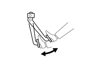
| (1) Start the engine and stop it after 1 or 2 minutes. Slowly depress the brake pedal several times. If the brake pedal can be depressed nearly to the floor the first time, but on the 2nd and 3rd time cannot be depressed as far, the brake booster assembly is airtight. |
|

(2) Depress the brake pedal with the engine running, and stop the engine with the brake pedal depressed.
If there is no change in the brake pedal reserve distance while holding the brake pedal depressed for 30 seconds, the brake booster assembly is airtight.
(b) Operation check
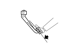
| (1) Depress the brake pedal several times with the ignition switch off and check that there is no change in the brake pedal reserve distance when the brake pedal is depressed. |
|
| (2) Depress and hold the brake pedal, then start the engine. If the brake pedal goes down slightly, operation is normal. |
|
READ NEXT:
 Removal
REMOVAL CAUTION / NOTICE / HINT
The necessary procedures (adjustment, calibration, initialization or registration) that must be performed after parts are removed and installed, or replaced during br
Disassembly
DISASSEMBLY PROCEDURE 1. REMOVE BRAKE VACUUM CHECK VALVE ASSEMBLY
(a) Remove the brake vacuum check valve assembly from the brake booster assembly.
(b) Remove the check valve grommet from the brak
Inspection
INSPECTION PROCEDURE 1. INSPECT BRAKE VACUUM CHECK VALVE ASSEMBLY
(a) Check that there is ventilation from the booster side to the engine side, and no ventilation from the engine side to the boo
SEE MORE:
Front Wiper Rubber
ComponentsCOMPONENTS ILLUSTRATION
*1 FRONT WIPER BLADE
*2 WIPER RUBBER
*3 FRONT WIPER RUBBER BACKING PLATE
- - RemovalREMOVAL CAUTION / NOTICE / HINT
NOTICE: Make sure to hold the front wiper arm while lifting it as lifting the front wiper arm by the front
Cruise Control Input Processor (P160700)
MONITOR DESCRIPTION The ECM continuously monitors its main and sub CPUs. This self-check ensures that the ECM is functioning properly. If outputs from the CPUs are different and deviate from the standard, the ECM will illuminate the MIL and store the DTC immediately.
DTC No. Detection Item
