Toyota Camry (XV70): Reassembly
REASSEMBLY
PROCEDURE
1. INSTALL BRAKE MASTER CYLINDER RESERVOIR STRAINER
2. INSTALL BRAKE MASTER CYLINDER RESERVOIR FILLER CAP ASSEMBLY
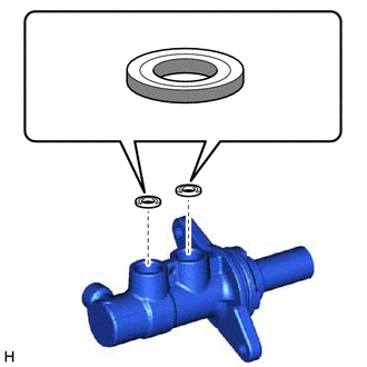
3. INSTALL MASTER CYLINDER RESERVOIR GROMMET
(a) Apply a light layer of lithium soap base glycol grease to the entire circumference of 2 new master cylinder reservoir grommets.
 |
Lithium Soap Base Glycol Grease |
(b) Install the 2 master cylinder reservoir grommets to the brake master cylinder body.
4. INSTALL BRAKE MASTER CYLINDER RESERVOIR ASSEMBLY
(a) Secure the brake master cylinder body in a vise.
NOTICE:
Place aluminum plates on the vise to prevent damage to the brake master cylinder body.
(b) Install the brake master cylinder reservoir assembly to the brake master cylinder body.
NOTICE:
Do not drop the brake master cylinder reservoir assembly.
5. INSTALL BRAKE MASTER CYLINDER STRAIGHT PIN
| (a) Using a 5 mm pin punch and a hammer, tap in the brake master cylinder straight pin to secure the brake master cylinder reservoir assembly. |
|
.png)
(b) Remove the brake master cylinder sub-assembly from the vise.
READ NEXT:
 Installation
INSTALLATION PROCEDURE 1. INSPECT AND ADJUST BRAKE BOOSTER PUSH ROD
Click here 2. INSTALL BRAKE MASTER CYLINDER O-RING
(a) Install a new brake master cylinder O-ring to the brake master cylinder
Components
COMPONENTS ILLUSTRATION
*1 BRAKE LINE
*2 BRAKE MASTER CYLINDER SUB-ASSEMBLY
Tightening torque for "Major areas involving basic vehicle performance such as moving/tur
SEE MORE:
Registration
REGISTRATION PROCEDURE 1. REGISTER TRANSMITTER CODE
HINT:
The vehicle garage door opener records transmitter codes for systems such as garage doors, gates, entry gates, door locks, home lighting systems, security systems or other transmitter code based systems.
The garage door opener is b
On-vehicle Inspection
ON-VEHICLE INSPECTION CAUTION / NOTICE / HINT
The necessary procedures (adjustment, calibration, initialization or registration) that must be performed after parts are removed and installed, or replaced when repairing air leaks in the intake system are shown below. Necessary Procedures After Parts
