Toyota Camry (XV70): Removal
REMOVAL
PROCEDURE
1. REMOVE FRONT WHEEL OPENING EXTENSION PAD RH
Click here .gif)
2. REMOVE FRONT WHEEL OPENING EXTENSION PAD LH
Click here
3. REMOVE NO. 1 ENGINE UNDER COVER
Click here
4. REMOVE NO. 2 ENGINE UNDER COVER ASSEMBLY
Click here
5. REMOVE V-RIBBED BELT
| (a) Release the V-ribbed belt tension by turning the V-ribbed belt tensioner assembly counterclockwise. |
|
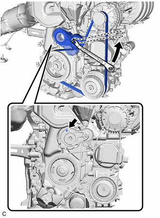
(b) Turn the V-ribbed belt tensioner assembly counterclockwise to align its holes, and then insert a 5 mm hexagon wrench to secure the V-ribbed belt tensioner assembly.
(c) Remove the V-ribbed belt from the V-ribbed belt tensioner assembly.
READ NEXT:
 Installation
INSTALLATION PROCEDURE 1. INSTALL V-RIBBED BELT
HINT: When reusing the V-ribbed belt, check the ribs and back of the V-ribbed belt for wear and cracks. If wear or a crack that reaches the core (at m
A25a-fks Oil And Oil Filter
ComponentsCOMPONENTS ILLUSTRATION
*1 CENTER NO. 4 ENGINE UNDER COVER
- - ILLUSTRATION
*1 OIL FILTER SUB-ASSEMBLY
*2 OIL FILLER CAP SUB-ASSEMBLY
*3
SEE MORE:
Brake Pressure Control Solenoid "A" Control Circuit Short to Battery (C13C012,...,C13C949)
DESCRIPTION The ABS solenoid relay and master cylinder cut solenoid valves are built into the brake actuator assembly.
Depending on the operating conditions, the master cylinder cut solenoid valves regulate the brake fluid pressure generated by the pump motor.
When this DTC is stored, the fail-s
Components
COMPONENTS ILLUSTRATION
*1 FRONT FENDER APRON SEAL LH
*2 FRONT FENDER APRON SEAL RH
*3 FRONT WHEEL OPENING EXTENSION PAD LH
*4 FRONT WHEEL OPENING EXTENSION PAD RH
*5 NO. 1 ENGINE UNDER COVER
*6 REAR ENGINE UNDER COVER LH
*7 REAR ENGI
© 2023-2026 Copyright www.tocamry.com
