Toyota Camry (XV70): Removal
REMOVAL
CAUTION / NOTICE / HINT
NOTICE:
If both left and right front flexible hoses are disconnected at the same time, be sure to place an identification mark on each hose to indicate its installation position.
HINT:
- Use the same procedure for the RH side and LH side.
- The following procedure is for the LH side.
PROCEDURE
1. REMOVE FRONT WHEEL
Click here .gif)
2. DRAIN BRAKE FLUID
NOTICE:
If brake fluid leaks onto any painted surface, immediately wash it off.
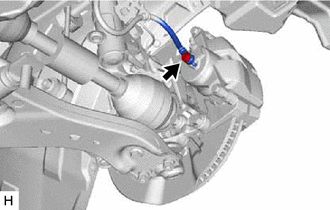
3. REMOVE FRONT FLEXIBLE HOSE
| (a) Remove the union bolt and gasket, and disconnect the front flexible hose from the front disc brake cylinder assembly. |
|
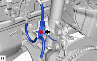
| (b) Remove the bolt and separate the front flexible hose from the front shock absorber assembly. |
|
| (c) Using a union nut wrench, disconnect the brake line while holding the front flexible hose with a wrench. NOTICE:
|
|
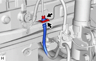
(d) Remove the clip and front flexible hose from the vehicle body.
READ NEXT:
 Installation
INSTALLATION CAUTION / NOTICE / HINT
NOTICE:
Because the left and right front flexible hoses are not interchangeable, verify the part number when installing the front flexible hoses.
When r
Components
COMPONENTS ILLUSTRATION
*1 FRONT DISC BRAKE ANTI-SQUEAL SHIM KIT
*2 FRONT DISC BRAKE PAD
*3 FRONT DISC BRAKE CYLINDER ASSEMBLY
*4 FRONT DISC BRAKE PAD WEAR INDICA
SEE MORE:
Terminals Of Ecu
TERMINALS OF ECU CHECK SKID CONTROL ECU (BRAKE ACTUATOR ASSEMBLY)
*a Front view of wire harness connector (to Skid Control ECU (Brake Actuator Assembly))
- -
(a) Disconnect the A34 skid control ECU (brake actuator assembly) connector.
(b) Measure the voltage and resistance
Left Rear Wheel Speed Sensor Circuit Short to Battery (C050C12)
DESCRIPTION Each speed sensor detects wheel speed and sends signals to the skid control ECU (brake actuator assembly). These signals are used by the ABS control.
The speed sensor detects the magnetic fields of the speed sensor rotor as it rotates and outputs a pulse signal.
The frequency of the
