Toyota Camry (XV70): Removal
REMOVAL
CAUTION / NOTICE / HINT
The necessary procedures (adjustment, calibration, initialization, or registration) that must be performed after parts are removed and installed, or replaced during navigation antenna assembly removal/installation are shown below.
Necessary Procedure After Parts Removed/Installed/Replaced|
Replaced Part or Performed Procedure |
Necessary Procedures | Effect/Inoperative Function when Necessary Procedure not Performed |
Link |
|---|---|---|---|
| Disconnect cable from negative battery terminal |
Perform steering sensor zero point calibration |
Lane Tracing Assist System |
|
|
Pre-collision System | |||
|
Memorize steering angle neutral point |
Parking Assist Monitor System |
| |
|
Panoramic View Monitor System |
|
CAUTION:
Some of these service operations affect the SRS airbag system. Read the precautionary notices concerning the SRS airbag system before servicing.
Click here .gif)
.png)
PROCEDURE
1. REMOVE INSTRUMENT PANEL SAFETY PAD SUB-ASSEMBLY
Click here
2. REMOVE NO. 3 HEATER TO REGISTER DUCT SUB-ASSEMBLY
Click here
3. REMOVE NAVIGATION ANTENNA ASSEMBLY WITH BRACKET
| (a) Disconnect the connector. |
|
.png)
(b) Disengage the 2 claws.
| (c) Remove the 2 screws and navigation antenna assembly with bracket. |
|
.png)
4. REMOVE NAVIGATION ANTENNA ASSEMBLY
(a) Disengage the 2 claws and 6 guides to remove the navigation antenna assembly as shown in the illustration.
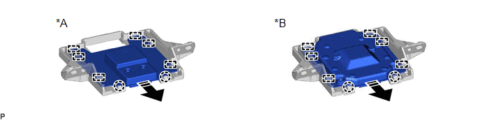
|
*A | w/o Manual (SOS) Switch |
*B | w/ Manual (SOS) Switch |
.png) |
Remove in this Direction |
- | - |
5. REMOVE NAVIGATION ANTENNA BRACKET
READ NEXT:
 Inspection
INSPECTION PROCEDURE 1. INSPECT NAVIGATION ANTENNA ASSEMBLY (w/o Manual (SOS) Switch)
(a) Check that the navigation antenna assembly cable is properly installed and does not have any sharp bends, pi
Installation
INSTALLATION PROCEDURE 1. INSTALL NAVIGATION ANTENNA BRACKET
2. INSTALL NAVIGATION ANTENNA ASSEMBLY (a) Engage the 6 guides and 2 claws to install the navigation antenna assembly as shown in the ill
SEE MORE:
Opening and closing the panoramic moon roof
Opens the panoramic moon roof*
Slide and hold the switch
backward. The panoramic moon
roof and electronic sunshade will
open automatically.
The panoramic moon roof can be
opened from the tilt-up position.
*: Quickly slide and release the
switch in either direction to stop the
panoramic
Replacing a flat tire
1. Chock the tires.
2. For vehicles with steel wheels,
remove the wheel ornament
using the wrench.
To protect the wheel ornament,
place a rag between the wrench
and the wheel ornament, as
shown in the illustration.
3. Slightly loosen the wheel nuts
(one turn).
Vehicles with wheel
