
Toyota Camry (XV70): Removal
REMOVAL
PROCEDURE
1. REMOVE NO. 1 METER HOOD CLUSTER
(a) Apply protective tape to the area shown in the illustration.
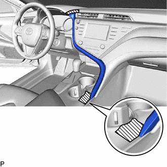
 |
Protective Tape |
(b) Disengage the 3 clips in the order shown in the illustration.
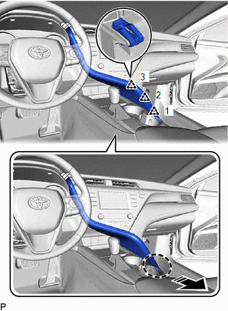
 |
Place Hand Here |
.png) |
Remove in this Direction |
(c) Disengage the 4 clips and 3 guides in the order shown in the illustration.
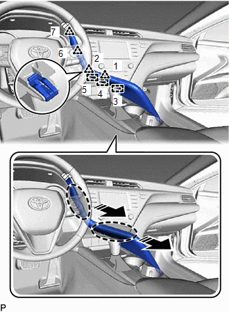
|
|
Place Hand Here |
|
|
Remove in this Direction |
(d) Disconnect the connector to remove the No. 1 meter hood cluster.
2. REMOVE NO. 2 INSTRUMENT PANEL GARNISH SUB-ASSEMBLY
(a) Disengage the 5 clips in the order shown in the illustration.
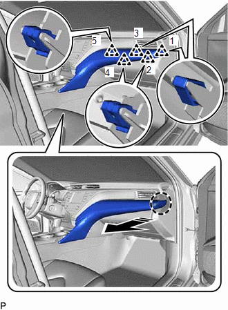
|
|
Place Hand Here |
|
|
Remove in this Direction |
(b) Disengage the 6 clips in the order shown in the illustration to remove the No. 2 instrument panel garnish sub-assembly.
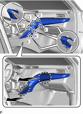
|
|
Place Hand Here |
|
|
Remove in this Direction |
3. REMOVE INSTRUMENT PANEL FINISH PLATE GARNISH
(a) Disengage the clip, claw and 2 guides to remove the instrument panel finish plate garnish as shown in the illustration.
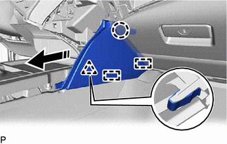
|
|
Remove in this Direction |
4. REMOVE LOWER CENTER INSTRUMENT PANEL FINISH PANEL
(a) Disengage the 2 clips as shown in the illustration.
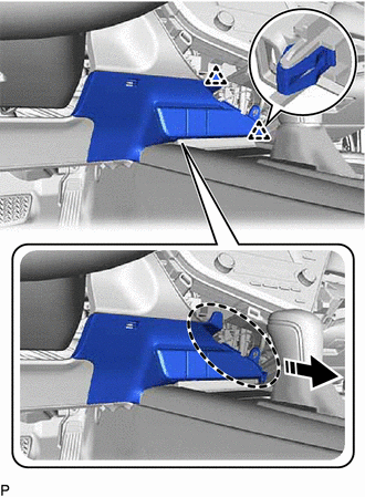
|
|
Place Hand Here |
|
|
Remove in this Direction |
(b) Disengage the 5 clips as shown in the illustration.
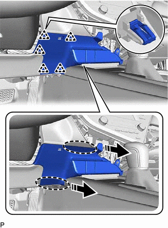
|
|
Place Hand Here |
|
|
Remove in this Direction |
(c) Disengage the clamp.
(d) Disconnect each connector to remove the lower center instrument panel finish panel.
5. REMOVE SHIFT LOCK RELEASE BUTTON COVER
for UB80E:
Click here
.gif)
for UA80E:
Click here
for UB80F:
Click here
6. REMOVE SHIFT LEVER KNOB SUB-ASSEMBLY
for UB80E:
Click here
for UA80E:
Click here
for UB80F:
Click here
7. REMOVE REAR UPPER CONSOLE PANEL SUB-ASSEMBLY
(a) Move the shift lever to N.
(b) Using a moulding remover, disengage the 2 claws and 2 clips as shown in the illustration.
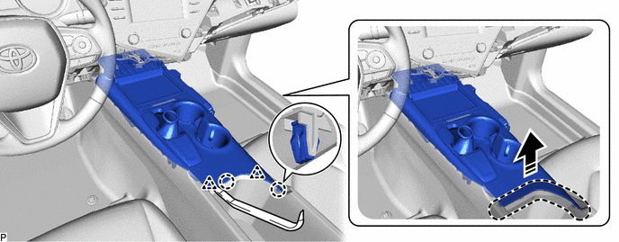
|
|
Insert Moulding Remover Here |
|
Remove in this Direction |
(c) Disengage the 5 claws and 4 clips as shown in the illustration.
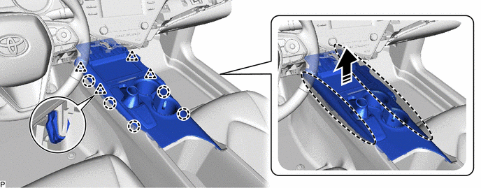
|
|
Place Hand Here |
|
Remove in this Direction |
(d) Disengage the clamp.
(e) Disconnect each connector to remove the rear upper console panel sub-assembly.
8. REMOVE SHIFT POSITION INDICATOR
for UB80E:
Click here
for UA80E:
Click here
for UB80F:
Click here
9. REMOVE FRONT CONSOLE BOX INSERT SUB-ASSEMBLY
| (a) Remove the 5 screws and front console box insert sub-assembly. |
|
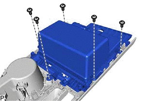
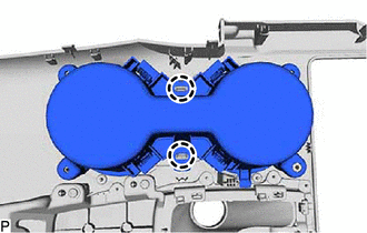
10. REMOVE INSTRUMENT PANEL CUP HOLDER
| (a) Remove the 3 screws. |
|
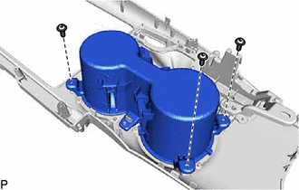
| (b) Disengage the 2 claws to remove the instrument panel cup holder. |
|
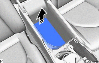
11. REMOVE CONSOLE BOX CARPET
(a) Remove the console box carpet as shown in the illustration.
|
|
Remove in this Direction |
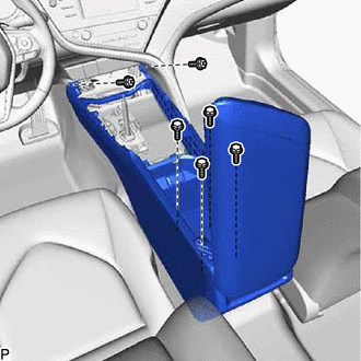
12. REMOVE CONSOLE BOX ASSEMBLY
| (a) Remove the 4 bolts, 2 screws and console box assembly. |
|
READ NEXT:
SEE MORE:
 Lost Communication With ECM/PCM "A" Missing Message (U010087,U010487,U012287)
DESCRIPTION The ECM communicates with each sensor and ECU via CAN communication.
If any malfunction is detected in a CAN communication circuit, one or more CAN communication system DTCs are stored.
DTC No. Detection Item
DTC Detection Condition Trouble Area
DTC Output from
Data List / Active Test
DATA LIST / ACTIVE TEST DATA LIST HINT:
Using the Techstream to read the Data List allows the values or states of switches, sensors, actuators and other items to be read without removing any parts. This non-intrusive inspection can be very useful because intermittent conditions or signals may be di
