Toyota Camry (XV70): System Diagram
Toyota Camry Repair Manual XV70 (2018-2024) / Vehicle Exterior / Lighting (ext) / Lighting System / System Diagram
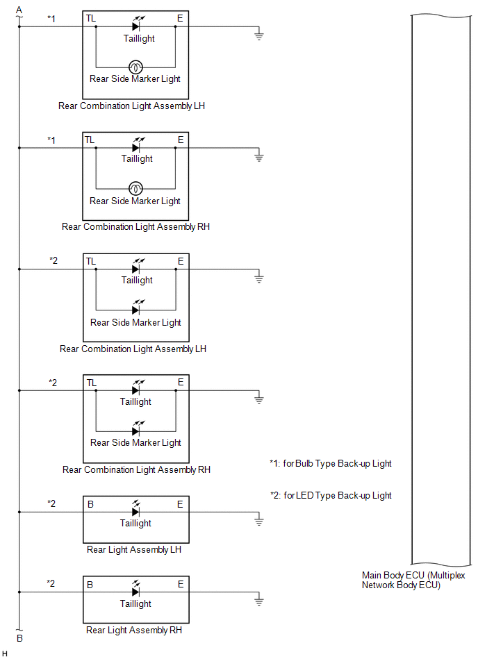
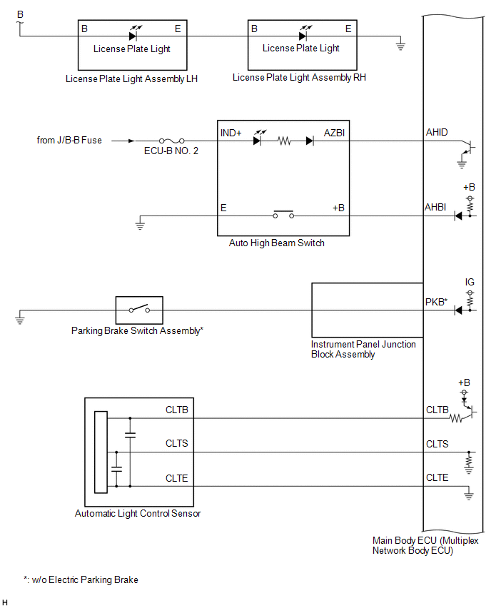
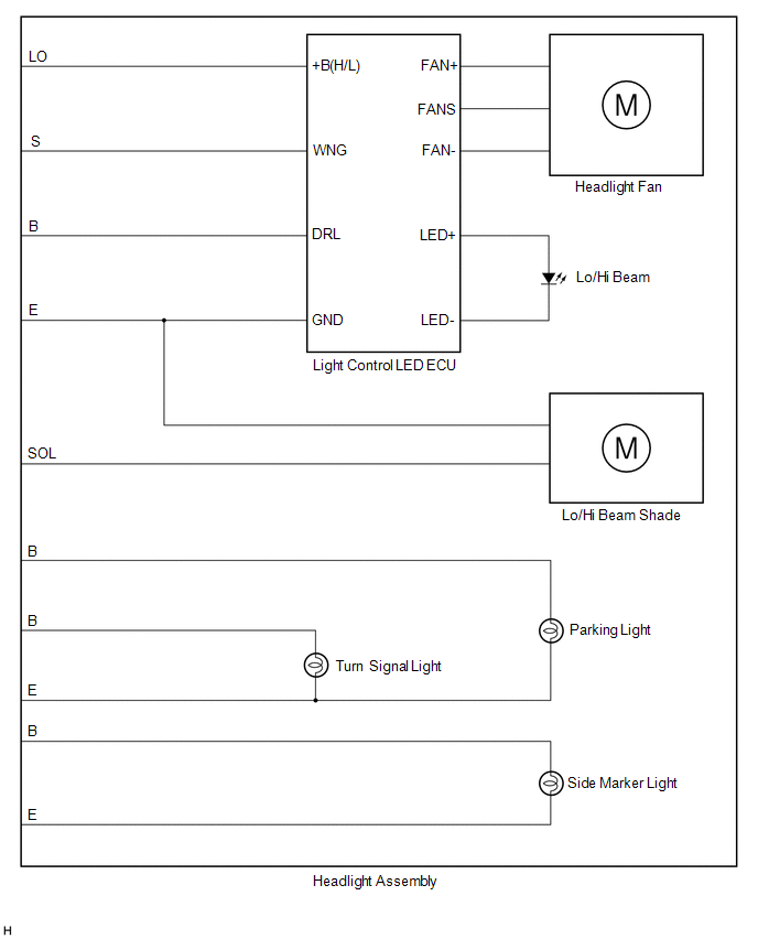
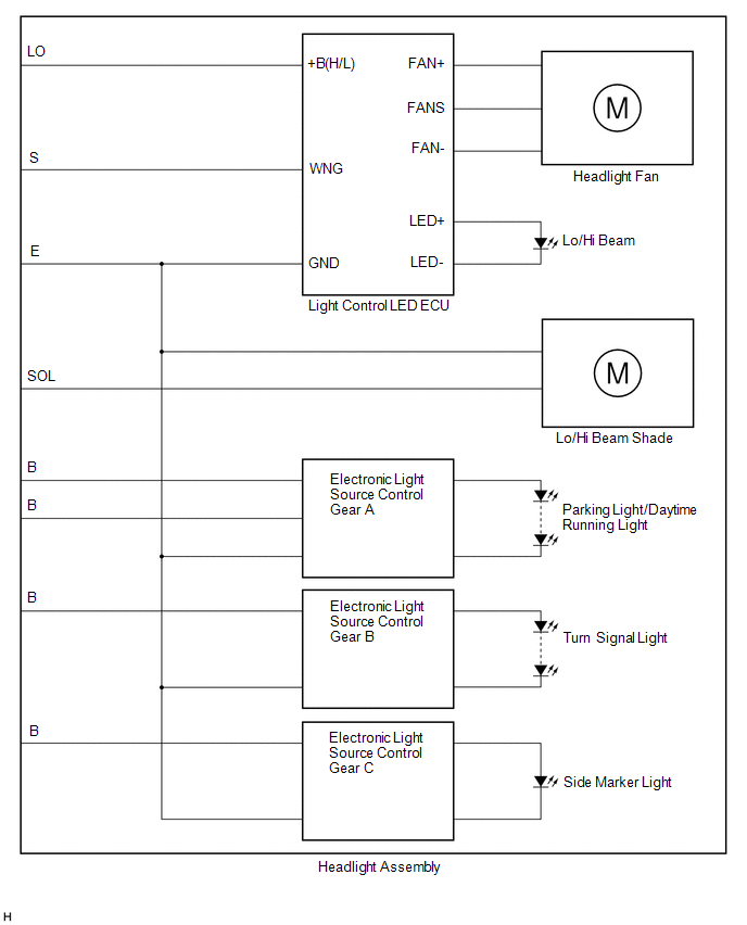
SYSTEM DIAGRAM
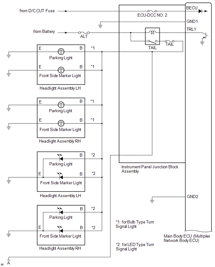
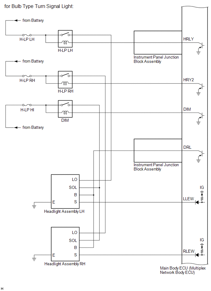
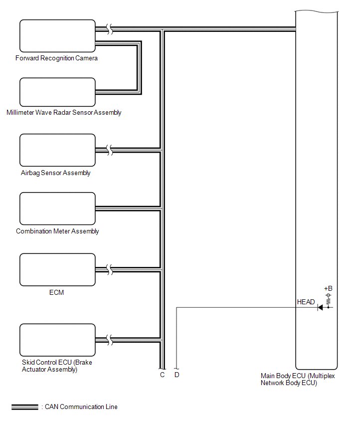
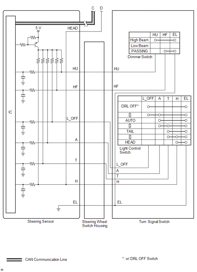
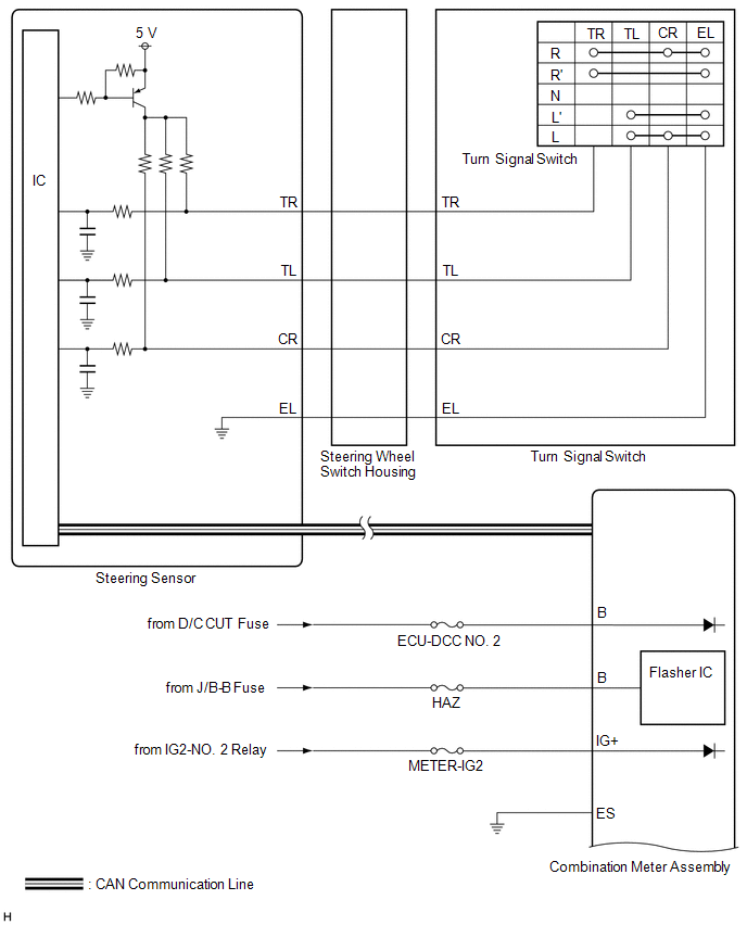
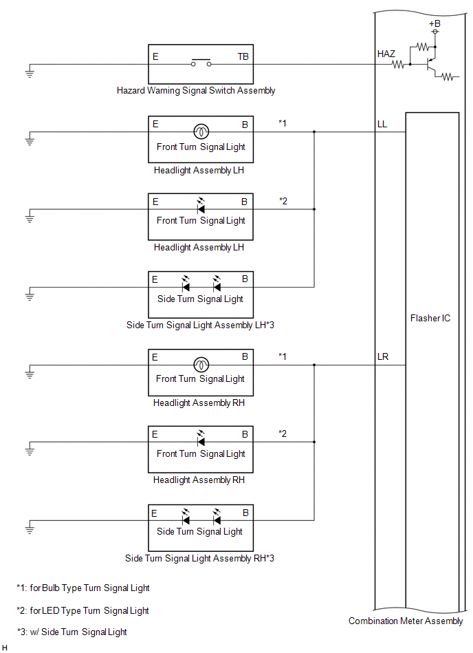
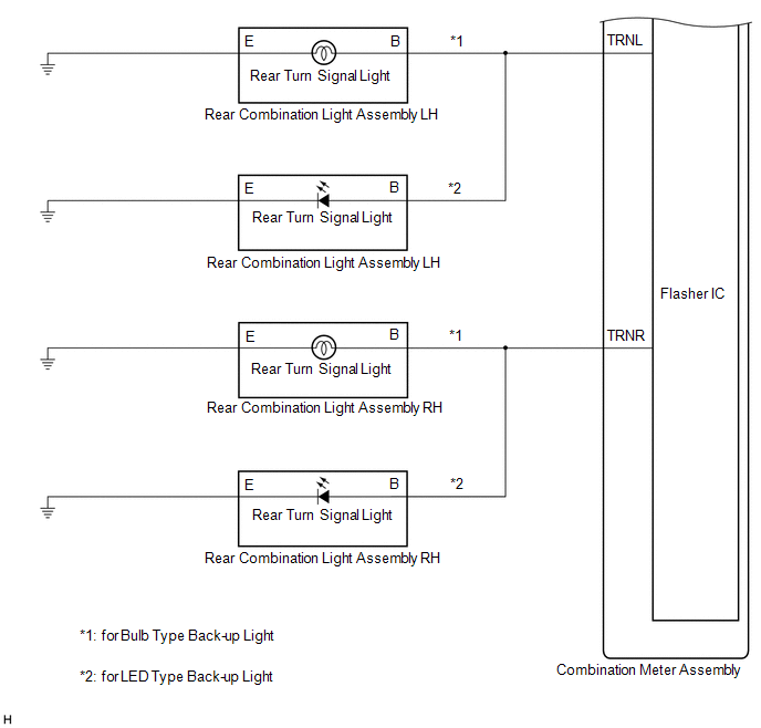
HEADLIGHT ASSEMBLY CIRCUIT (for Bulb Type Turn Signal Light)
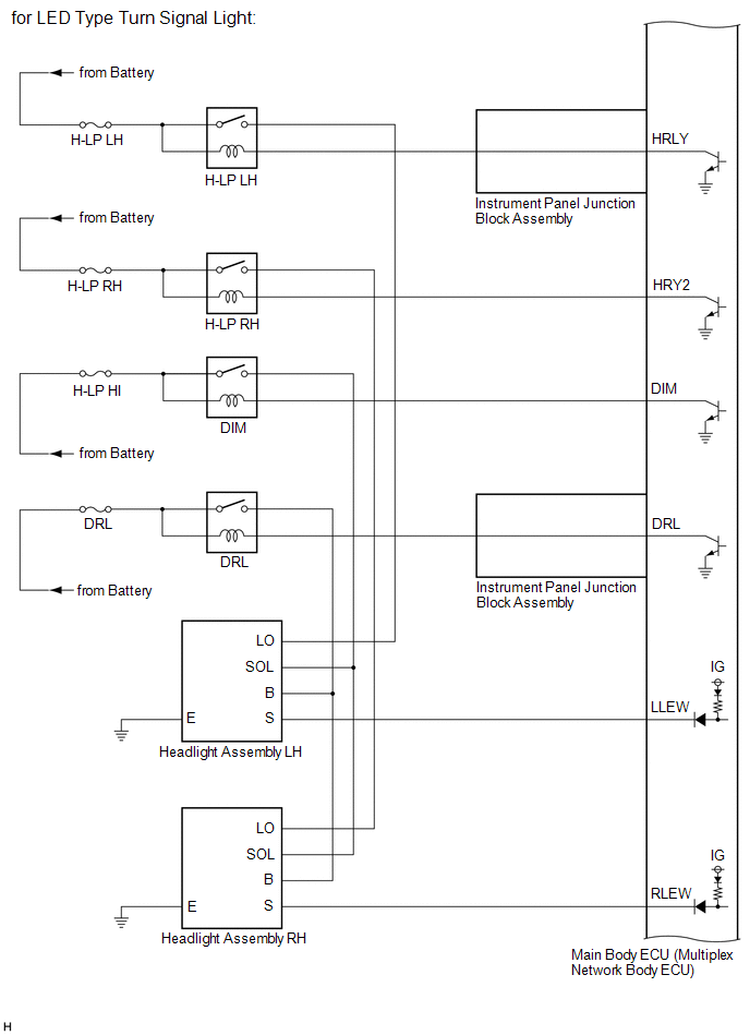
HEADLIGHT ASSEMBLY CIRCUIT (for LED Type Turn Signal Light)
READ NEXT:
 How To Proceed With Troubleshooting
CAUTION / NOTICE / HINT
HINT:
Use the following procedure to troubleshoot the lighting system.
*: Use the Techstream.
PROCEDURE
1. VEHICLE BROUGHT TO WORKSHOP
Operation Check
OPERATION CHECK AUTOMATIC LIGHT CONTROL SYSTEM OPERATION CHECK
NOTICE: Make sure that the customize settings are set to default when performing the automatic light control system operation check.
Customize Parameters
CUSTOMIZE PARAMETERS CUSTOMIZE LIGHTING SYSTEM (EXT)
NOTICE:
When the customer requests a change in a function, first make sure that the function can be customized.
Be sure to make a n
SEE MORE:
Automatic High Beam Switch Indicator does not Come ON
DESCRIPTION When the automatic high beam system is on, the main body ECU (multiplex network body ECU) illuminates the auto high beam switch indicator. WIRING DIAGRAM
CAUTION / NOTICE / HINT
NOTICE:
Inspect the fuses for circuits related to this system before performing the following pro
Crankshaft Position Sensor "A" Circuit Intermittent (P03351F,P03352A,P033531)
DESCRIPTION Refer to DTC P033511. Click here
DTC No. Detection Item
DTC Detection Condition Trouble Area
MIL Memory
Note P03351F
Crankshaft Position Sensor "A" Circuit Intermittent
Under conditions (a), (b) and (c), no crankshaft position sensor signal
© 2023-2026 Copyright www.tocamry.com
