Toyota Camry (XV70): Terminals Of Ecu
TERMINALS OF ECU
CHECK TIRE PRESSURE WARNING ECU AND RECEIVER
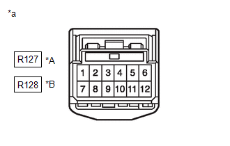
(a) Disconnect the R127 or R128 tire pressure warning ECU and receiver connector and measure the voltage or resistance on the wire harness side.
|
*A | w/ Smart Key System |
|
*B | w/o Smart Key System |
|
*a | Front view of wire harness connector (to Tire Pressure Warning ECU and Receiver) |
|
Terminal No. (Symbol) | Wiring Color |
Terminal Description | Condition |
Specified Condition |
|---|---|---|---|---|
|
R127-1 (IG) - R127-12 (GND) |
LA-B - W-B | IG power source |
Ignition switch ON | 10 to 16 V |
|
R127-7 (+B) - R127-12 (GND) |
LA-R - W-B | Power supply (from battery) |
Always | 10 to 16 V |
|
R127-9 (CANH) - R127-10 (CANL)* |
L - W | CAN communication line |
Ignition switch off | 54 to 69 Ω |
|
R127-12 (GND) - Body ground |
W-B - Body ground | Ground |
Always | Below 1 Ω |
- *: w/ Tire Inflation Pressure Display Function
|
Terminal No. (Symbol) | Wiring Color |
Terminal Description | Condition |
Specified Condition |
|---|---|---|---|---|
|
R128-1 (IG) - R128-12 (GND) |
LA-LG - W-B*2 LA-B - W-B*3 |
IG power source | Ignition switch ON |
10 to 16 V |
|
R128-7 (+B) - R128-12 (GND) |
LA-L - W-B | Power supply (from battery) |
Always | 10 to 16 V |
|
R128-9 (CANH) - R128-10 (CANL)*1 |
L - W | CAN communication line |
Ignition switch off | 54 to 69 Ω |
|
R128-12 (GND) - Body ground |
W-B - Body ground | Ground |
Always | Below 1 Ω |
- *1: w/ Tire Inflation Pressure Display Function
- *2: w/ Blind Spot Monitor System
- *3: w/o Blind Spot Monitor System
(b) Connect the R127 or R128 tire pressure warning ECU and receiver connector.
(c) Measure the voltage according to the value(s) in the table below. If the result is not as specified, the ECU may be malfunctioning.
HINT:
Measure the values on the wire harness side while the connector is connected.

|
*A | w/ Smart Key System |
*B | w/o Smart Key System |
|
*a | Component with harness connected (Tire Pressure Warning ECU and Receiver) |
- | - |
|
Terminal No. (Symbol) | Wiring Color |
Terminal Description | Condition |
Specified Condition |
|---|---|---|---|---|
|
R127-3 (CLSW) - R127-12 (GND) |
SB - W-B |
Tire pressure warning reset switch |
| Below 1.5 V |
| 8 to 15 V | |||
|
R127-4 (RDA) - R127-12 (GND) |
GR - W-B | Output signals |
Ignition switch ON | Pulse generation (see waveform 1) |
|
R127-5 (PRG) - R127-12 (GND) |
R - W-B | Input signals |
Ignition switch ON | Pulse generation (see waveform 1) |
|
Terminal No. (Symbol) | Wiring Color |
Terminal Description | Condition |
Specified Condition |
|---|---|---|---|---|
|
R128-3 (CLSW) - R128-12 (GND) |
SB - W-B |
Tire pressure warning reset switch |
| Below 1.5 V |
| 8 to 15 V | |||
|
R128-4 (RDA) - R128-12 (GND) |
GR - W-B | Output signals |
Ignition switch ON | Pulse generation (see waveform 1) |
|
R128-5 (PRG) - R128-12 (GND) |
R - W-B | Input signals |
Ignition switch ON | Pulse generation (see waveform 1) |
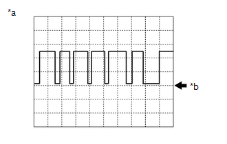
(d) Using an oscilloscope, check waveform 1.
|
*a | Example |
|
*b | GND |
|
Item | Contents |
|---|---|
|
Terminal | R127-4 (RDA) - R127-12 (GND)*1 R128-4 (RDA) - R128-12 (GND)*2 R127-5 (PRG) - R127-12 (GND)*1 R128-5 (PRG) - R128-12 (GND)*2 |
|
Tool setting | 5 V/DIV, 5 ms./DIV. |
|
Vehicle condition | Ignition switch ON |
- *1: w/ Smart Key System
- *2: w/o Smart Key System
HINT:
The waveform shown in the illustration is an example. If the tester displays a waveform that alternates between high and low, where high is a voltage that is between the IG power source voltage and a voltage 2.2 V lower than the IG power source voltage, and where low is a voltage of between 0 and 1.2 V, the ECU can be judged normal.
READ NEXT:
 Diagnosis System
DIAGNOSIS SYSTEM CHECK WARNING LIGHT
NOTICE:
When there is a problem with the tire pressure warning system, the tire pressure warning light blinks at 0.5 second intervals, and illuminates after
Dtc Check / Clear
DTC CHECK / CLEAR CHECK DTC (for TIRE PRESSURE WARNING ECU AND RECEIVER)
(a) Turn the ignition switch off. (b) Connect the Techstream to the DLC3.
(c) Turn the ignition switch to ON. (d) Turn the
Fail-safe Chart
FAIL-SAFE CHART FAIL-SAFE FUNCTION (a) When a malfunction occurs in the tire pressure warning system, the tire pressure warning light illuminates after blinking for 1 minute to inform the driver of th
SEE MORE:
Removal
REMOVAL CAUTION / NOTICE / HINT
The necessary procedures (adjustment, calibration, initialization or registration) that must be performed after parts are removed and installed, or replaced during fuel injector assembly removal/installation are shown below. Necessary Procedures After Parts Removed/
Replacement
REPLACEMENT CAUTION / NOTICE / HINT
The necessary procedures (adjustment, calibration, initialization or registration) that must be performed after parts are removed and installed, or replaced during transfer case oil seal removal/installation are shown below. Necessary Procedures After Parts Remo
