Toyota Camry (XV70): Washer Level Warning Switch
Components
COMPONENTS
ILLUSTRATION
|
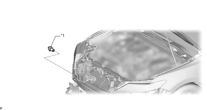
*1 | LEVEL WARNING SWITCH ASSEMBLY |
- | - |
Removal
REMOVAL
CAUTION / NOTICE / HINT
The necessary procedures (adjustment, calibration, initialization or registration) that must be performed after parts are removed and installed, or replaced during level warning switch assembly removal/installation are shown below.
Necessary Procedure After Parts Removed/Installed/Replaced|
Replaced Part or Performed Procedure |
Necessary Procedure | Effect/Inoperative Function when Necessary Procedure not Performed |
Link |
|---|---|---|---|
| *: Applies only for when removing and installing or replacing the rear television camera assembly. | |||
| Front bumper assembly (w/ Panoramic view monitor system) |
Front television camera view adjustment |
Panoramic view monitor system |
|
Replacement or removal and installation of 2 or more parts:
|
| ||
PROCEDURE
1. REMOVE FRONT BUMPER ASSEMBLY
Click here
.gif)
2. DRAIN WASHER FLUID
Click here
3. REMOVE LEVEL WARNING SWITCH ASSEMBLY
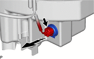
(a) Disconnect the connector.
.png) |
Remove in this Direction |
(b) Remove the level warning switch assembly as shown in the illustration.
Inspection
INSPECTION
PROCEDURE
1. INSPECT LEVEL WARNING SWITCH ASSEMBLY
HINT:
This check should be performed with the level warning switch assembly installed on the washer jar.
| (a) Fill the washer jar with washer fluid. |
|
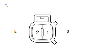
(b) Measure the resistance according to the value(s) in the table below.
Standard Resistance:
|
Tester Connection | Condition |
Specified Condition |
|---|---|---|
|
1 (S) - 2 (E) | Fluid volume is 600 to 800 cc (36.6 to 48.8 cu.in.) or higher* |
10 kΩ or higher |
|
Fluid volume is 600 to 800 cc (36.6 to 48.8 cu.in.) or lower* |
Below 1 Ω |
HINT:
*: The level warning switch assembly begins operating when the fluid volume is 600 to 800 cc (36.6 to 48.8 cu.in.) depending on the vehicle condition.
If the result is not as specified, replace the level warning switch assembly.
Installation
INSTALLATION
PROCEDURE
1. INSTALL LEVEL WARNING SWITCH ASSEMBLY
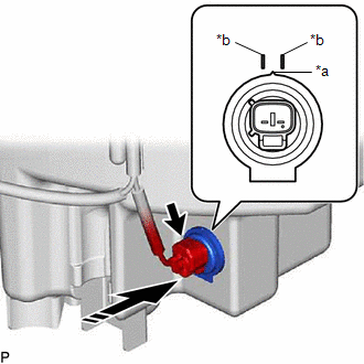
(a) Install the level warning switch assembly as shown in the illustration.
|
*a | Protrusion |
|
*b | Marking |
.png) |
Install in this Direction |
NOTICE:
Make sure that the protrusion of the level warning switch assembly is between the 2 markings.
(b) Connect the connector.
2. ADD WASHER FLUID
Click here
.gif)
3. INSTALL FRONT BUMPER ASSEMBLY
Click here
READ NEXT:
 Washer Motor
ComponentsCOMPONENTS ILLUSTRATION
*1 FRONT FENDER LINER RH
*2 FRONT WHEEL OPENING EXTENSION PAD RH
*3 WINDSHIELD WASHER MOTOR AND PUMP ASSEMBLY
- - Remov
Washer Nozzle
ComponentsCOMPONENTS ILLUSTRATION
*1 WASHER NOZZLE SUB-ASSEMBLY
- -
● Non-reusable part
- - On-vehicle InspectionON-VEHICLE INSPECTION PROCEDURE
SEE MORE:
Components
COMPONENTS ILLUSTRATION
*1 REAR ENGINE UNDER COVER LH
*2 FRONT FENDER APRON SEAL LH
*3 NO. 1 ENGINE UNDER COVER
*4 FRONT WHEEL OPENING EXTENSION PAD LH
*5 FRONT WHEEL OPENING EXTENSION PAD RH
- -
N*m (kgf*cm, ft.*lbf): Specified
On-vehicle Inspection
ON-VEHICLE INSPECTION PROCEDURE
1. OPERATION CHECK (a) Slide the clip and disconnect the union to check valve hose from the vacuum pump assembly.
(b) Connect the hose of the vacuum gauge to the vacuum pump assembly.
*a Vacuum Gauge
*b Plug
