Toyota Camry (XV70): Components
COMPONENTS
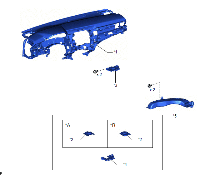
ILLUSTRATION
|
*A | w/o Manual (SOS) Switch |
*B | w/ Manual (SOS) Switch |
|
*1 | INSTRUMENT PANEL SAFETY PAD SUB-ASSEMBLY |
*2 | NAVIGATION ANTENNA ASSEMBLY |
|
*3 | NAVIGATION ANTENNA ASSEMBLY WITH BRACKET |
*4 | NAVIGATION ANTENNA BRACKET |
|
*5 | NO. 3 HEATER TO REGISTER DUCT SUB-ASSEMBLY |
- | - |
READ NEXT:
 Removal
REMOVAL CAUTION / NOTICE / HINT
The necessary procedures (adjustment, calibration, initialization, or registration) that must be performed after parts are removed and installed, or replaced during n
Inspection
INSPECTION PROCEDURE 1. INSPECT NAVIGATION ANTENNA ASSEMBLY (w/o Manual (SOS) Switch)
(a) Check that the navigation antenna assembly cable is properly installed and does not have any sharp bends, pi
Installation
INSTALLATION PROCEDURE 1. INSTALL NAVIGATION ANTENNA BRACKET
2. INSTALL NAVIGATION ANTENNA ASSEMBLY (a) Engage the 6 guides and 2 claws to install the navigation antenna assembly as shown in the ill
SEE MORE:
Disassembly
DISASSEMBLY PROCEDURE 1. REMOVE BRAKE VACUUM CHECK VALVE ASSEMBLY
(a) Remove the brake vacuum check valve assembly from the brake booster assembly.
(b) Remove the check valve grommet from the brake booster assembly. 2. REMOVE VACUUM WARNING SWITCH ASSEMBLY
(a) Remove the vacuum warning switch
Removal
REMOVAL CAUTION / NOTICE / HINT
The necessary procedures (adjustment, calibration, initialization or registration) that must be performed after parts are removed and installed, or replaced during front door belt moulding removal/installation are shown below. Necessary Procedure After Parts Remove
© 2023-2026 Copyright www.tocamry.com
