Toyota Camry (XV70): Components
COMPONENTS
ILLUSTRATION
|
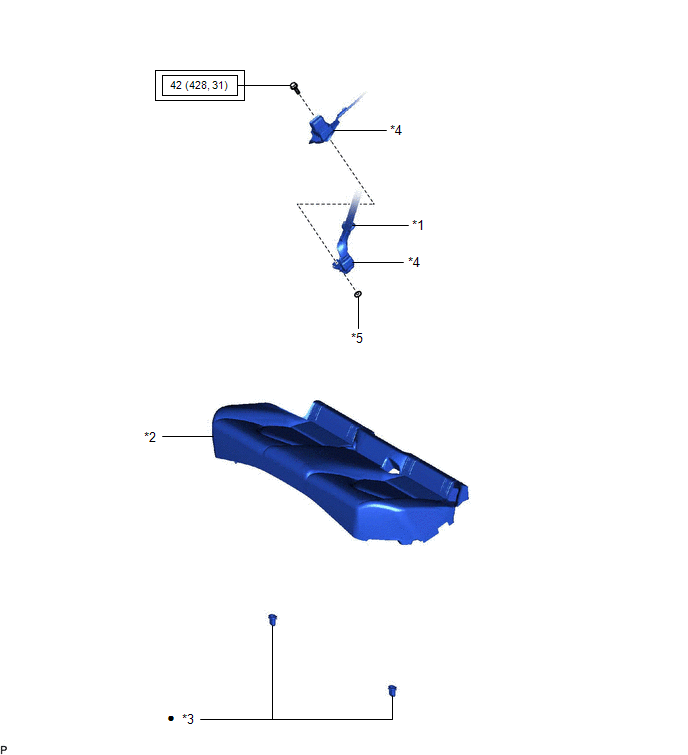
*1 | REAR CENTER SEAT OUTER BELT ASSEMBLY |
*2 | REAR SEAT CUSHION ASSEMBLY |
|
*3 | REAR SEAT CUSHION LOCK HOOK |
*4 | REAR SEAT INNER BELT ASSEMBLY RH |
|
*5 | WASHER |
- | - |
.png) |
Tightening torque for "Major areas involving basic vehicle performance such as moving/turning/stopping": N*m (kgf*cm, ft.*lbf) |
● | Non-reusable part |
ILLUSTRATION
|
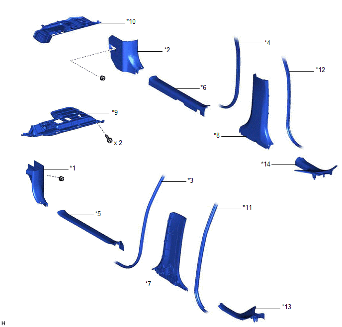
*1 | COWL SIDE TRIM SUB-ASSEMBLY LH |
*2 | COWL SIDE TRIM SUB-ASSEMBLY RH |
|
*3 | FRONT DOOR OPENING TRIM WEATHERSTRIP LH |
*4 | FRONT DOOR OPENING TRIM WEATHERSTRIP RH |
|
*5 | FRONT DOOR SCUFF PLATE LH |
*6 | FRONT DOOR SCUFF PLATE RH |
|
*7 | LOWER CENTER PILLAR GARNISH LH |
*8 | LOWER CENTER PILLAR GARNISH RH |
|
*9 | NO. 1 INSTRUMENT PANEL UNDER COVER SUB-ASSEMBLY |
*10 | NO. 2 INSTRUMENT PANEL UNDER COVER SUB-ASSEMBLY |
|
*11 | REAR DOOR OPENING TRIM WEATHERSTRIP LH |
*12 | REAR DOOR OPENING TRIM WEATHERSTRIP RH |
|
*13 | REAR DOOR SCUFF PLATE LH |
*14 | REAR DOOR SCUFF PLATE RH |
ILLUSTRATION
|
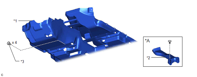
*A | for Dual Type |
- | - |
|
*1 | FRONT FLOOR CARPET ASSEMBLY |
*2 | NO. 1 CONSOLE BOX DUCT |
|
*3 | FRONT FLOOR CARPET CLIP |
- | - |
ILLUSTRATION
|
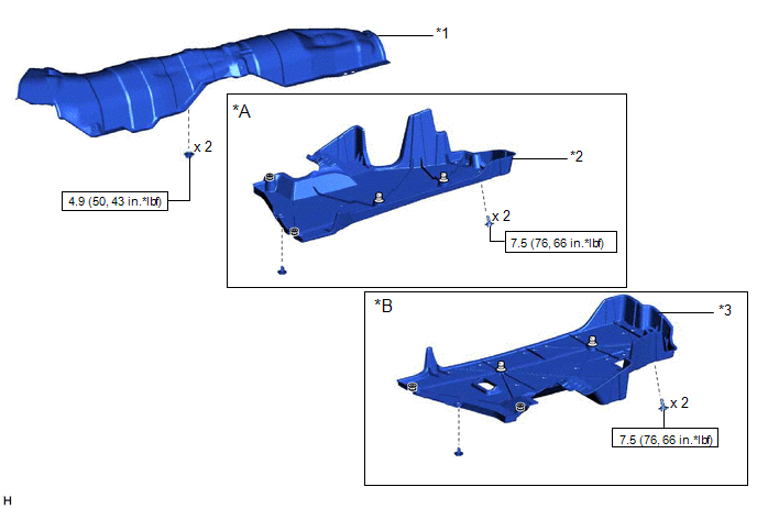
*A | for RH Side |
*B | for LH Side |
|
*1 | FRONT LOWER NO. 1 FLOOR HEAT INSULATOR |
*2 | NO. 1 FLOOR UNDER COVER |
|
*3 | NO. 2 FLOOR UNDER COVER |
- | - |
.png) |
N*m (kgf*cm, ft.*lbf): Specified torque |
- | - |
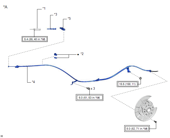
ILLUSTRATION
|
*A | for Type A |
- | - |
|
*1 | NO. 1 PARKING BRAKE CABLE ASSEMBLY |
*2 | NO. 1 PARKING BRAKE CABLE CLAMP |
|
*3 | NO. 1 PARKING BRAKE PULL ROD SUB-ASSEMBLY |
*4 | NO. 3 PARKING BRAKE CABLE ASSEMBLY |
|
*5 | PARKING BRAKE EQUALIZER |
- | - |
|
|
Tightening torque for "Major areas involving basic vehicle performance such as moving/turning/stopping": N*m (kgf*cm, ft.*lbf) |
● | Non-reusable part |
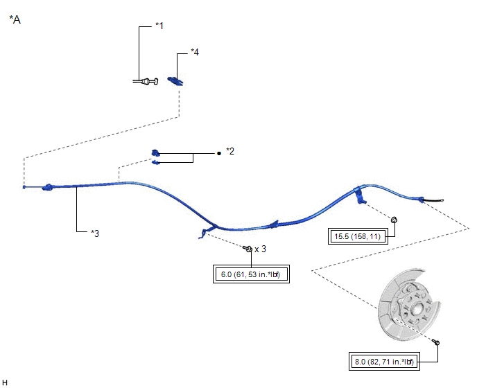
ILLUSTRATION
|
*A | for Type B |
- | - |
|
*1 | NO. 1 PARKING BRAKE CABLE ASSEMBLY |
*2 | NO. 1 PARKING BRAKE CABLE CLAMP |
|
*3 | NO. 3 PARKING BRAKE CABLE ASSEMBLY |
*4 | PARKING BRAKE EQUALIZER |
|
|
Tightening torque for "Major areas involving basic vehicle performance such as moving/turning/stopping": N*m (kgf*cm, ft.*lbf) |
● | Non-reusable part |
READ NEXT:
 Removal
REMOVAL CAUTION / NOTICE / HINT
The necessary procedures (adjustment, calibration, initialization, or registration) that must be performed after parts are removed and installed, or replaced during N
Installation
INSTALLATION CAUTION / NOTICE / HINT
HINT: Use the same procedure for the No. 2 parking brake cable assembly and No. 3 parking brake cable assembly. PROCEDURE
1. INSTALL NO. 1 PARKING BRAKE CABLE
SEE MORE:
Terminals Of Ecu
TERMINALS OF ECU CHECK WINDSHIELD WIPER MOTOR ASSEMBLY
(a) Disconnect the A31 windshield wiper motor assembly connector.
(b) Measure the voltage and resistance on the wire harness side connector according to the value(s) in the table below.
Terminal No. (Symbol)
Wiring Color Te
On-vehicle Inspection
ON-VEHICLE INSPECTION PROCEDURE
1. INSPECT FUEL CUT OPERATION (a) Start the engine. (b) Warm up the engine.
(c) Increase the engine speed to approximately 3500 rpm. (d) Use a sound scope to check for fuel injector assembly operating sounds.
(e) When the accelerator pedal is fully released, che
