Toyota Camry (XV70): Components
COMPONENTS
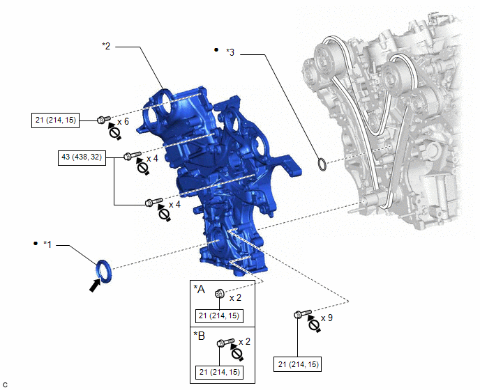
ILLUSTRATION
|
*A | w/ Stud Bolt |
*B | w/o Stud Bolt |
|
*1 | TIMING CHAIN CASE OIL SEAL |
*2 | TIMING CHAIN COVER ASSEMBLY |
|
*3 | OIL PUMP GASKET |
- | - |
.png) |
N*m (kgf*cm, ft.*lbf): Specified torque |
● | Non-reusable part |
.png) |
MP Grease |
.png) |
Do not apply lubricants to the threaded parts |
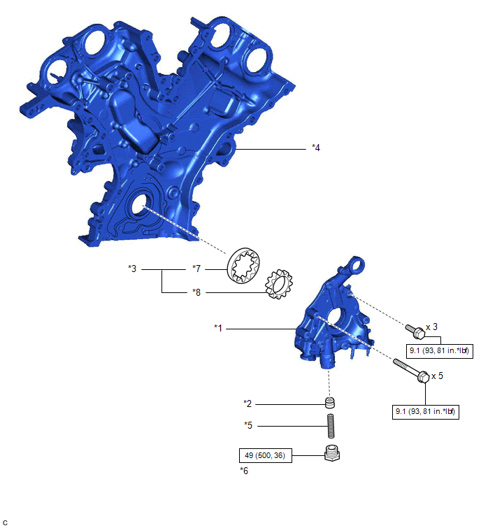
ILLUSTRATION
|
*1 | OIL PUMP COVER |
*2 | OIL PUMP RELIEF VALVE |
|
*3 | OIL PUMP ROTOR SET |
*4 | TIMING CHAIN COVER ASSEMBLY |
|
*5 | OIL PUMP RELIEF VALVE SPRING |
*6 | OIL PUMP RELIEF VALVE PLUG |
|
*7 | DRIVEN ROTOR |
*8 | DRIVE ROTOR |
|
|
N*m (kgf*cm, ft.*lbf): Specified torque |
- | - |
READ NEXT:
 Removal
REMOVAL CAUTION / NOTICE / HINT
The necessary procedures (adjustment, calibration, initialization, or registration) that must be performed after parts are removed and installed, or replaced during o
Disassembly
DISASSEMBLY PROCEDURE 1. REMOVE OIL PUMP RELIEF VALVE
(a) Using a 27 mm socket wrench, remove the oil pump relief valve plug from the oil pump cover.
(b) Remove the oil pump
Inspection
INSPECTION PROCEDURE 1. INSPECT OIL PUMP RELIEF VALVE
(a) Coat the oil pump relief valve with engine oil and check that it falls smoothly into the valve hole by its own weight.
HINT: If the o
SEE MORE:
Removal
REMOVAL CAUTION / NOTICE / HINT
The necessary procedures (adjustment, calibration, initialization, or registration) that must be performed after parts are removed and installed, or replaced during rear trailing arm assembly removal/installation are shown below. Necessary Procedures After Parts Rem
Diagnostic Trouble Code Chart
DIAGNOSTIC TROUBLE CODE CHART Automatic Transaxle System
DTC No. Detection Item
MIL Memory
Note Link
P050031 Vehicle Speed Sensor "A" No Signal
Comes on DTC stored
SAE Code: P0500
P056014 System Voltage Circuit Short to Ground or Open
© 2023-2026 Copyright www.tocamry.com
