Toyota Camry (XV70): Removal
REMOVAL
CAUTION / NOTICE / HINT
The necessary procedures (adjustment, calibration, initialization, or registration) that must be performed after parts are removed and installed, or replaced during oil pump removal/installation are shown below.
Necessary Procedure After Parts Removed/Installed/Replaced|
Replaced Part or Performed Procedure |
Necessary Procedure | Effect/Inoperative Function when Necessary Procedure not Performed |
Link |
|---|---|---|---|
| *1: When the ECM is replaced with a new one, reset memory is unnecessary. | |||
| Battery terminal is disconnected/reconnected |
Perform steering sensor zero point calibration |
Lane Tracing Assist System |
|
|
Pre-collision System | |||
|
Memorize steering angle neutral point |
Parking Assist Monitor System |
| |
|
Panoramic view monitor system |
| ||
|
Replacement of ECM | Vehicle Identification Number (VIN) registration |
MIL comes on |
|
|
ECU communication ID registration (Immobiliser system) |
Engine start function |
| |
| Inspection After Repair |
|
|
|
Replacement of automatic transaxle assembly |
|
|
|
|
Replacement of ECM (If possible, read the transaxle compensation code from the previous ECM) |
| ||
| Replacement of ECM (If impossible, read the transaxle compensation code from the previous ECM) |
| ||
| Replacement of ECM |
Code registration |
|
|
|
Replacement of automatic transaxle fluid |
ATF thermal degradation estimate reset |
The value of the Data List item "ATF Thermal Degradation Estimate" is not estimated correctly. |
|
|
Suspension, tires, etc. (The vehicle height changes because of suspension or tire replacement) |
Rear television camera assembly optical axis (Back camera position setting) |
Parking assist monitor system |
|
|
Replacement of front bumper assembly |
Front television camera view adjustment |
Panoramic view monitor system |
|
|
Suspension, tires, etc. (The vehicle height changes because of suspension or tire replacement) |
| ||
| Front wheel alignment adjustment |
|
|
|
PROCEDURE
1. REMOVE OIL PAN SUB-ASSEMBLY
Click here
.gif)
2. REMOVE TIMING CHAIN CASE OIL SEAL
Click here
3. REMOVE TIMING CHAIN COVER ASSEMBLY
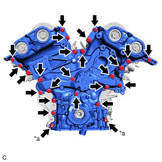
| (a) w/ Stud Bolt: (1) Remove the 23 bolts and 2 nuts shown in the illustration. |
|
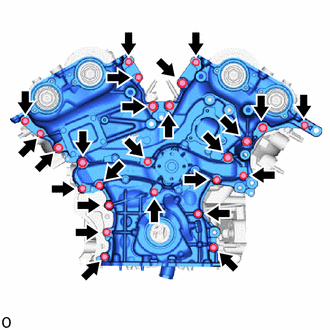
| (b) w/o Stud Bolt: (1) Remove the 25 bolts shown in the illustration. |
|
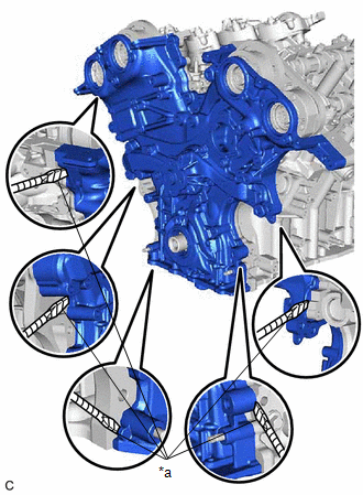
| (c) Remove the timing chain cover assembly by prying between the timing chain cover assembly and cylinder head sub-assembly or cylinder block sub-assembly with a screwdriver with its tip wrapped with protective tape. NOTICE: Be careful not to damage the contact surfaces of the cylinder head sub-assembly, cylinder block sub-assembly and timing chain cover assembly. |
|
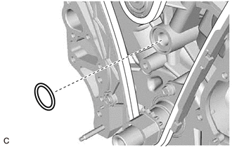
| (d) Remove the oil pump gasket from the cylinder block sub-assembly. |
|
READ NEXT:
 Disassembly
DISASSEMBLY PROCEDURE 1. REMOVE OIL PUMP RELIEF VALVE
(a) Using a 27 mm socket wrench, remove the oil pump relief valve plug from the oil pump cover.
(b) Remove the oil pump
Inspection
INSPECTION PROCEDURE 1. INSPECT OIL PUMP RELIEF VALVE
(a) Coat the oil pump relief valve with engine oil and check that it falls smoothly into the valve hole by its own weight.
HINT: If the o
Reassembly
REASSEMBLY PROCEDURE 1. INSTALL OIL PUMP ROTOR SET
(a) Coat the drive rotor and driven rotor with engine oil and place them into the timing chain cover assembly with the rotor marks facing up. C
SEE MORE:
Removal
REMOVAL CAUTION / NOTICE / HINT
The necessary procedures (adjustment, calibration, initialization, or registration) that must be performed after parts are removed and installed, or replaced during spark plug removal/installation are shown below. Necessary Procedures After Parts Removed/Installed/R
Brake Warning Light does not Come ON
DESCRIPTION The skid control ECU (brake actuator assembly) controls the brake system warning light (red indicator) in the combination meter assembly via CAN communication. CAUTION / NOTICE / HINT
NOTICE: After replacing the skid control ECU (brake actuator assembly), perform acceleration sensor ze
