Toyota Camry (XV70): Parts Location
PARTS LOCATION
ILLUSTRATION
|
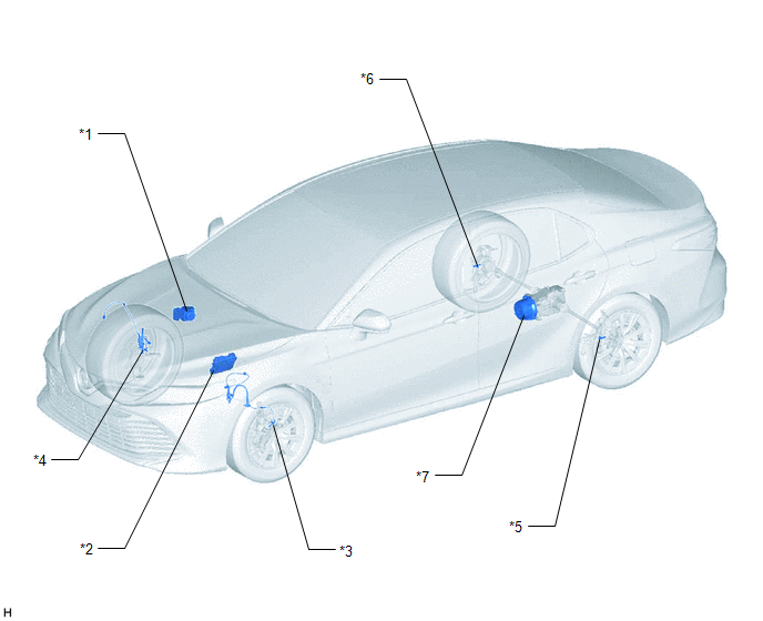
*1 | BRAKE ACTUATOR ASSEMBLY - SKID CONTROL ECU | *2 |
ECM |
| *3 |
FRONT SPEED SENSOR LH |
*4 | FRONT SPEED SENSOR RH |
|
*5 | REAR SKID CONTROL SENSOR LH |
*6 | REAR SKID CONTROL SENSOR RH |
|
*7 | TRANSMISSION COUPLING ASSEMBLY - 4WD LINEAR SOLENOID |
- | - |
ILLUSTRATION
|
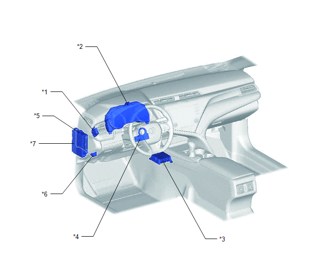
*1 | 4WD ECU ASSEMBLY |
*2 | COMBINATION METER ASSEMBLY - AWD WARNING MESSAGE (MULTI-INFORMATION DISPLAY) |
|
*3 | AIRBAG SENSOR ASSEMBLY - YAW RATE AND ACCELERATION SENSOR |
*4 | STEERING SENSOR |
|
*5 | MAIN BODY ECU (MULTIPLEX NETWORK BODY ECU) |
*6 | DLC3 |
|
*7 | INSTRUMENT PANEL JUNCTION BLOCK ASSEMBLY - ECU-DCC NO. 1 FUSE - ECU-IG1 NO. 2 FUSE |
- | - |
READ NEXT:
 System Diagram
SYSTEM DIAGRAM
How To Proceed With Troubleshooting
CAUTION / NOTICE / HINT
HINT:
Use the following procedure listed to troubleshoot the Dynamic Torque Control AWD System.
*: Use the Techstream.
PROCEDURE
1. VEHICLE BROUGHT TO W
Calibration
CALIBRATION
NOTICE:
Initial AWD functions such as acceleration are sometimes affected unless backup memory is cleared.
When the yaw rate and acceleration sensor (airbag sensor assembly) is
SEE MORE:
Left Rear Wheel Speed Sensor Circuit Intermittent (C050C1F)
DESCRIPTION Refer to DTC C050C12 Click here
DTC No. Detection Item
DTC Detection Condition Trouble Area
C050C1F Left Rear Wheel Speed Sensor Circuit Intermittent
The speed sensor signal is excessively noisy.
The calculated change in wheel speed is more t
Telephone And Gps Antenna Cords (for Front Side)
ComponentsCOMPONENTS ILLUSTRATION
*1 INSTRUMENT PANEL SAFETY PAD SUB-ASSEMBLY
*2 NO. 2 SIDE DEFROSTER NOZZLE DUCT
*3 NO. 3 HEATER TO REGISTER DUCT SUB-ASSEMBLY
*4 TELEPHONE AND GPS ANTENNA CORD RemovalREMOVAL CAUTION / NOTICE / HINT
The necessary procedures
© 2023-2026 Copyright www.tocamry.com
