Toyota Camry (XV70): Parts Location
Toyota Camry Repair Manual XV70 (2018-2024) / Engine, Hybrid System / Cruise Control / Road Sign Assist System / Parts Location
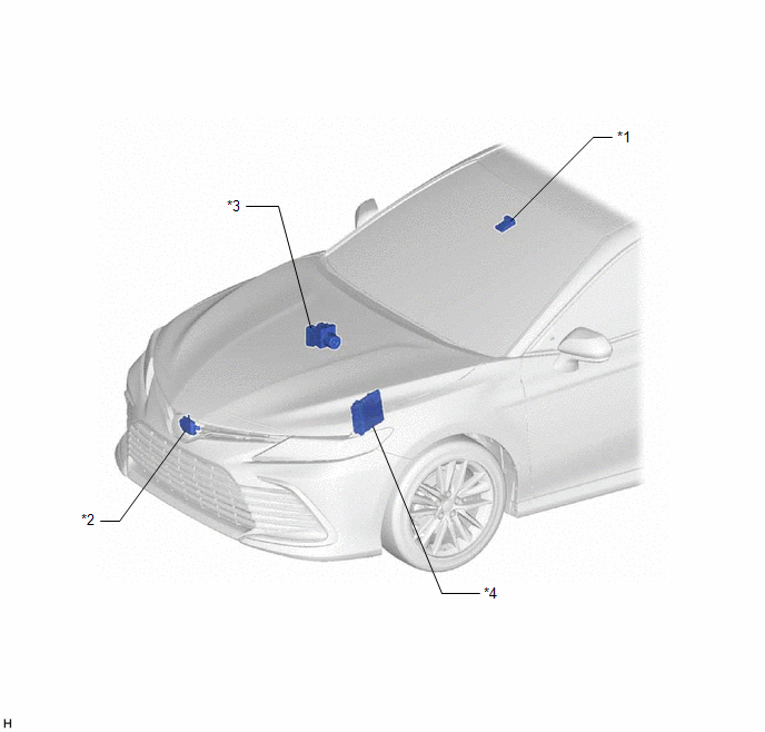
PARTS LOCATION
ILLUSTRATION
|
*1 | FORWARD RECOGNITION CAMERA |
*2 | MILLIMETER WAVE RADAR SENSOR ASSEMBLY |
|
*3 | SKID CONTROL ECU (BRAKE ACTUATOR ASSEMBLY) |
*4 | ECM |
ILLUSTRATION
|
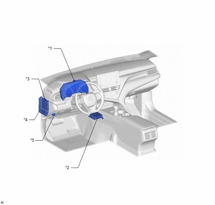
*1 | COMBINATION METER ASSEMBLY |
*2 | AIRBAG SENSOR ASSEMBLY |
|
*3 | MAIN BODY ECU (MULTIPLEX NETWORK BODY ECU) |
*4 | INSTRUMENT PANEL JUNCTION BLOCK ASSEMBLY - ECU-IG1 NO. 3 FUSE |
|
*5 | DLC3 |
- | - |
READ NEXT:
 System Diagram
SYSTEM DIAGRAM
How To Proceed With Troubleshooting
CAUTION / NOTICE / HINT
HINT:
Before performing troubleshooting for the road sign assist system, make sure that the pre-collision system and lane tracing assist system are not malfunctioning.
Customize Parameters
CUSTOMIZE PARAMETERS
NOTICE:
When the customer requests a change in a function, first make sure that the function can be customized.
Be sure to make a note of the current settings before cu
SEE MORE:
Customize Parameters
CUSTOMIZE PARAMETERS CUSTOMIZE TELEMATICS SYSTEM
(a) Customizing with the Techstream.
NOTICE:
When the customer requests a change in a function, first make sure that the function can be customized.
Be sure to make a note of the current settings before customizing.
When troubleshooti
Components
COMPONENTS ILLUSTRATION
*1 NO. 1 VACUUM SWITCHING VALVE ASSEMBLY (for ACIS)
*2 VACUUM HOSE SUB-ASSEMBLY
*3 V-BANK COVER SUB-ASSEMBLY
- -
N*m (kgf*cm, ft.*lbf): Specified torque
- -
© 2023-2026 Copyright www.tocamry.com
