
Toyota Camry (XV70): Reassembly
Toyota Camry Repair Manual XV70 (2018-2024) / Brake / Brake System (other) / Brake Booster / Reassembly
REASSEMBLY
PROCEDURE
1. INSTALL VACUUM WARNING SWITCH ASSEMBLY
(a) Install a new check valve grommet to the brake booster assembly.
(b) Install the vacuum warning switch assembly to the brake booster assembly as shown in the illustration.
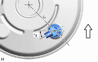
|
*a | 30 |
READ NEXT:
 Installation
INSTALLATION PROCEDURE 1. INSTALL BRAKE BOOSTER GASKET
(a) Install a new brake booster gasket to the brake booster assembly. 2. INSTALL BRAKE BOOSTER ASSEMBLY
(a) Temporarily install the brake boo
Components
COMPONENTS ILLUSTRATION
*1 BRAKE MASTER CYLINDER RESERVOIR FILLER CAP ASSEMBLY
- - ILLUSTRATION
*A except 2-Pot Caliper
*B for 2-Pot Caliper
*C w/o
SEE MORE:
Terminals Of Ecu
TERMINALS OF ECU CHECK MAIN BODY ECU (MULTIPLEX NETWORK BODY ECU) AND INSTRUMENT PANEL JUNCTION BLOCK ASSEMBLY
(a) Disconnect the instrument panel junction block assembly and main body ECU (multiplex network body ECU) connectors.
(b) Measure the voltage and resistance according to the value(s
Removal
REMOVAL CAUTION / NOTICE / HINT
The necessary procedures (adjustment, calibration, initialization or registration) that must be performed after parts are removed and installed, or replaced during transfer assembly removal/installation are shown below. Necessary Procedures After Parts Removed/Insta
© 2023-2026 Copyright www.tocamry.com
