Toyota Camry (XV70): Removal
REMOVAL
CAUTION / NOTICE / HINT
HINT:
- Use the same procedure for the RH side and LH side.
- The following procedure is for the LH side.
PROCEDURE
1. PRECAUTION
Click here
.gif)
2. RELEASE PARKING BRAKE
(a) Move the shift lever to P.
(b) Turn the engine switch on (IG).
(c) Operate the electric parking brake switch assembly to release the parking brake.
HINT:
If the parking brake cannot be released:
Click here
(d) Turn the engine switch off.
3. REMOVE REAR WHEEL
Click here
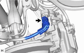
4. DISCONNECT NO. 2 PARKING BRAKE WIRE ASSEMBLY
| (a) Disconnect the No. 2 parking brake wire assembly connector from the parking brake actuator assembly. NOTICE:
|
|
5. REMOVE PARKING BRAKE ACTUATOR ASSEMBLY
| (a) Using a 5 mm hexagon socket wrench, remove the 2 bolts and parking brake actuator assembly from the rear disc brake cylinder assembly. NOTICE:
|
|
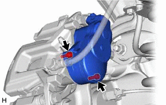
(b) Remove the O-ring from the rear disc brake cylinder assembly.
READ NEXT:
 Inspection
INSPECTION PROCEDURE 1. INSPECT PARKING BRAKE ACTUATOR ASSEMBLY
(a) Parking brake actuator assembly operation inspection
(1) Apply voltage to the terminals of the parking brake actuator assemb
Installation
INSTALLATION CAUTION / NOTICE / HINT
HINT:
Use the same procedure for the RH side and LH side.
The following procedure is for the LH side.
PROCEDURE 1. INSTALL PARKING BRAKE ACTUATOR ASS
Electric Parking Brake Switch
ComponentsCOMPONENTS ILLUSTRATION
*1 ELECTRIC PARKING BRAKE SWITCH ASSEMBLY
- - RemovalREMOVAL PROCEDURE
1. PRECAUTION Click here
2. REMOVE REAR UPPER CONSOLE PANEL SUB-AS
SEE MORE:
Power windows
Opening and closing procedures
The power windows can be opened and closed using the switches.
Operating the switch moves the windows as follows:
Closing
One-touch closing*
Opening
One-touch opening*
*: To stop the window partway, operate
the switch in the opposite direction.
Pre
Installation
INSTALLATION PROCEDURE 1. INSTALL FUEL PIPE PLUG SUB-ASSEMBLY
(a) Install a new O-ring, No. 1 fuel injector back-up ring, No. 2 fuel injector back-up ring and No. 3 fuel injector back-up ring to the fuel pipe plug sub-assembly as shown in the illustration.
*1 Fuel Pipe Plug Sub-assemb
