Toyota Camry (XV70): Replacement
REPLACEMENT
PROCEDURE
1. REMOVE FRONT WHEEL OPENING EXTENSION PAD RH
Click here .gif)
2. REMOVE FRONT WHEEL OPENING EXTENSION PAD LH
Click here
3. REMOVE NO. 1 ENGINE UNDER COVER
Click here
4. REMOVE NO. 2 ENGINE UNDER COVER ASSEMBLY
Click here
5. DRAIN TRANSFER OIL
(a) Stop the vehicle on a level surface.
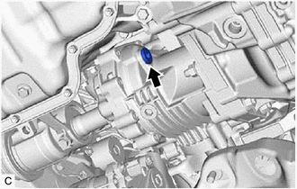
| (b) Using a 10 mm straight hexagon wrench and 10 x 12 mm long offset wrench, remove the transfer filler plug and gasket from the transfer assembly. |
|
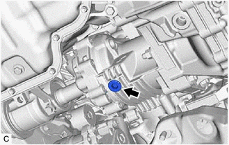
| (c) Using a 10 mm hexagon socket wrench, remove the transfer drain plug and gasket from the transfer assembly and drain the transfer oil. |
|
(d) Using a 10 mm straight hexagon wrench and 10 x 12 mm long offset wrench, temporarily install the transfer filler plug and gasket to the transfer assembly.
HINT:
Reuse the old gasket as the transfer filler plug will be removed again.
(e) Using a 10 mm hexagon socket wrench, install the transfer drain plug and a new gasket to the transfer assembly.
Torque:
39 N
READ NEXT:
 Rear Brake Flexible Hose (w/ Electric Parking Brake System)
ComponentsCOMPONENTS ILLUSTRATION
*1 REAR FLEXIBLE HOSE
*2 GASKET
*3 UNION BOLT
*4 BRAKE LINE
Tightening torque for "Major areas involving basic ve
Rear Brake Flexible Hose (w/o Electric Parking Brake System)
ComponentsCOMPONENTS ILLUSTRATION
*1 REAR FLEXIBLE HOSE
*2 GASKET
*3 UNION BOLT
- -
Tightening torque for "Major areas involving basic vehicle perf
SEE MORE:
Reassembly
REASSEMBLY PROCEDURE 1. INSTALL SOLENOID (SL) VALVE
(a) Coat the solenoid (SL) valve with Toyota Genuine ATF WS.
(b) Install the solenoid (SL) valve to the transmission valve body assembly with the bolt.
Torque: 7.0 N
Transmitter Battery(w/ Smart Key System)
ComponentsCOMPONENTS ILLUSTRATION
*1 TRANSMITTER BATTERY
*2 MECHANICAL KEY
*3 TRANSMITTER HOUSING COVER
*4 TRANSMITTER HOUSING CASE
*5 SMART KEY DOOR CONTROL TRANSMITTER HOUSING SET
- - RemovalREMOVAL PROCEDURE
1. REMOVE TRANSMITTER BATTER
