Toyota Camry (XV70): Steering Pad Switch Circuit
DESCRIPTION
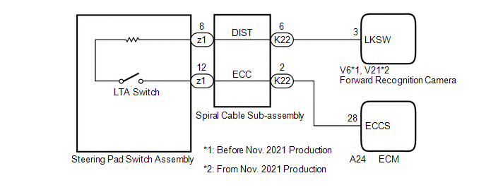
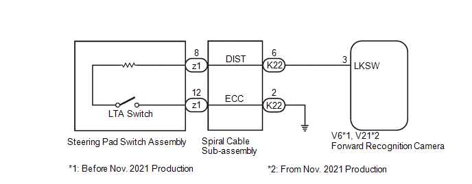
The forward recognition camera receives LTA switch signals from the steering pad switch assembly.
WIRING DIAGRAM
for A25A-FKS
for 2GR-FKS
CAUTION / NOTICE / HINT
NOTICE:
The vehicle is equipped with a Supplemental Restraint System (SRS) which includes components such as airbags. Before servicing (including removal or installation of parts), be sure to read the precaution for Supplemental Restraint System.
Click here .gif)
PROCEDURE
| 1. |
READ VALUE USING TECHSTREAM (Lane Control) |
(a) Read the Data List according to the display on the Techstream.
Chassis > Lane Control > Data List|
Tester Display | Measurement Item |
Range | Normal Condition |
Diagnostic Note |
|---|---|---|---|---|
|
LDA Control | Whether lane tracing assist system control is permitted or not |
Prohibit or Permit | Prohibit: Lane tracing assist system control not possible Permit: Lane tracing assist system control possible |
- |
|
Tester Display |
|---|
| LDA Control |
|
Result | Proceed to |
|---|---|
|
The value of the Data List item changes in accordance with the operation of the LTA switch |
A |
| The value of the Data List item does not change in accordance with the operation of the LTA switch |
B |
| A |
.gif) | PROCEED TO NEXT SUSPECTED AREA SHOWN IN PROBLEM SYMPTOMS TABLE |
|
.gif)
| 2. |
INSPECT STEERING PAD SWITCH ASSEMBLY |
Click here
| NG | | REPLACE STEERING PAD SWITCH ASSEMBLY |
|
| 3. |
INSPECT SPIRAL CABLE SUB-ASSEMBLY |
Click here
| NG | | REPLACE SPIRAL CABLE SUB-ASSEMBLY |
|
| 4. |
CHECK HARNESS AND CONNECTOR (SPIRAL CABLE SUB-ASSEMBLY - FORWARD RECOGNITION CAMERA) |
(a) Disconnect the V6*1, V21*2 forward recognition camera connector.
- *1: Before Nov. 2021 Production
- *2: From Nov. 2021 Production
(b) Measure the resistance according to the value(s) in the table below.
Standard Resistance:
Before Nov. 2021 Production|
Tester Connection | Condition |
Specified Condition |
|---|---|---|
|
K22-6 (DIST) - V6-3 (LKSW) |
Always | Below 1 Ω |
|
K22-6 (DIST) or V6-3 (LKSW) - Body ground |
Always | 10 kΩ or higher |
|
Tester Connection | Condition |
Specified Condition |
|---|---|---|
|
K22-6 (DIST) - V21-3 (LKSW) |
Always | Below 1 Ω |
|
K22-6 (DIST) or V21-3 (LKSW) - Body ground |
Always | 10 kΩ or higher |
|
Result | Proceed to |
|---|---|
|
OK (for A25A-FKS) | A |
|
OK (for 2GR-FKS) | B |
|
NG | C |
| B |
| GO TO STEP 6 |
| C |
| REPAIR OR REPLACE HARNESS OR CONNECTOR |
|
| 5. |
CHECK HARNESS AND CONNECTOR (SPIRAL CABLE SUB-ASSEMBLY - ECM) |
(a) Disconnect the A24 ECM connector.
(b) Measure the resistance according to the value(s) in the table below.
Standard Resistance:
|
Tester Connection | Condition |
Specified Condition |
|---|---|---|
|
K22-2 (ECC) - A24-28 (ECCS) |
Always | Below 1 Ω |
|
K22-2 (ECC) or A24-28 (ECCS) - Body ground |
Always | 10 kΩ or higher |
| OK | | PROCEED TO NEXT SUSPECTED AREA SHOWN IN PROBLEM SYMPTOMS TABLE |
| NG | | REPAIR OR REPLACE HARNESS OR CONNECTOR |
| 6. |
CHECK HARNESS AND CONNECTOR (SPIRAL CABLE SUB-ASSEMBLY - BODY GROUND) |
(a) Measure the resistance according to the value(s) in the table below.
Standard Resistance:
|
Tester Connection | Condition |
Specified Condition |
|---|---|---|
|
K22-2 (ECC) - Body ground |
Always | Below 1 Ω |
| OK | | PROCEED TO NEXT SUSPECTED AREA SHOWN IN PROBLEM SYMPTOMS TABLE |
| NG | | REPAIR OR REPLACE HARNESS OR CONNECTOR |
READ NEXT:
 Indicator Circuit
DESCRIPTION The LTA indicator output request signal is sent from the forward recognition camera to the combination meter assembly via CAN communication. CAUTION / NOTICE / HINT
NOTICE: When replacin
Components
COMPONENTS ILLUSTRATION
*1 COOL AIR INTAKE DUCT SEAL
*2 MILLIMETER WAVE RADAR SENSOR ASSEMBLY
N*m (kgf*cm, ft.*lbf): Specified torque
- -
SEE MORE:
Receiver Error (C2176)
DESCRIPTION Tire pressure warning valve and transmitter signals are transmitted to the tire pressure warning ECU and receiver in the vehicle as radio waves.
DTC No. Detection Item
DTC Detection Condition Trouble Area
Note C2176
Receiver Error Malfunction in the tire p
Problem Symptoms Table
PROBLEM SYMPTOMS TABLE
NOTICE:
Before replacing the main body ECU (multiplex network body ECU), refer to Registration.*
Click here
When replacing the combination meter assembly, always replace it with a new one. If a combination meter assembly which was installed to another vehi
