Toyota Camry (XV70): Components
Toyota Camry Repair Manual XV70 (2018-2024) / General / Maintenance / Gf1a Transfer Oil / Components
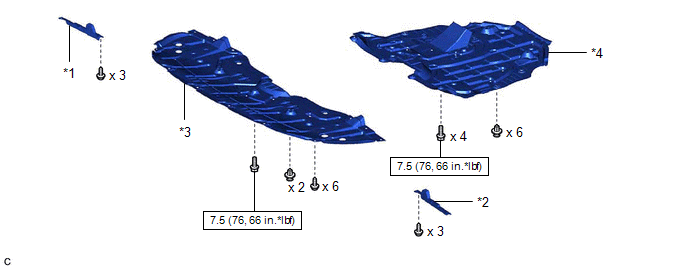
COMPONENTS
ILLUSTRATION
|
*1 | FRONT WHEEL OPENING EXTENSION PAD RH |
*2 | FRONT WHEEL OPENING EXTENSION PAD LH |
|
*3 | NO. 1 ENGINE UNDER COVER |
*4 | NO. 2 ENGINE UNDER COVER ASSEMBLY |
.png) |
N*m (kgf*cm, ft.*lbf): Specified torque |
- | - |
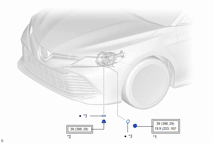
ILLUSTRATION
|
*1 | TRANSFER FILLER PLUG |
*2 | TRANSFER DRAIN PLUG |
|
*3 | GASKET |
- | - |
.png) |
Tightening torque for "Major areas involving basic vehicle performance such as moving/turning/stopping": N*m (kgf*cm, ft.*lbf) |
* | For use with SST and a union nut wrench |
|
● | Non-reusable part |
- | - |
READ NEXT:
 Replacement
REPLACEMENT PROCEDURE 1. REMOVE FRONT WHEEL OPENING EXTENSION PAD RH
Click here
2. REMOVE FRONT WHEEL OPENING EXTENSION PAD LH Click here
3. REMOVE NO. 1 ENGINE UNDER COVER
Click h
Rear Brake Flexible Hose (w/ Electric Parking Brake System)
ComponentsCOMPONENTS ILLUSTRATION
*1 REAR FLEXIBLE HOSE
*2 GASKET
*3 UNION BOLT
*4 BRAKE LINE
Tightening torque for "Major areas involving basic ve
Rear Brake Flexible Hose (w/o Electric Parking Brake System)
ComponentsCOMPONENTS ILLUSTRATION
*1 REAR FLEXIBLE HOSE
*2 GASKET
*3 UNION BOLT
- -
Tightening torque for "Major areas involving basic vehicle perf
SEE MORE:
Replacement
REPLACEMENT CAUTION / NOTICE / HINT
The necessary procedures (adjustment, calibration, initialization, or registration) that must be performed after parts are removed and installed, or replaced during automatic transaxle fluid replacement are shown below. Necessary Procedures After Parts Removed/I
Brake Hold Operated Indicator Light Circuit
DESCRIPTION The brake hold operated indicator light illuminates when the brake hold system is operating (vehicle stopped due to brake fluid pressure hold) and turns off when the brake hold system operation is finished (brake fluid pressure decreases).
The brake hold system may not operate dependin
© 2023-2026 Copyright www.tocamry.com
